Remote Start Wiring, 2008 Toyota Prius
Printed From: the12volt.com
Forum Name: Car Security and Convenience
Forum Discription: Car Alarms, Keyless Entries, Remote Starters, Immobilizer Bypasses, Sensors, Door Locks, Window Modules, Heated Mirrors, Heated Seats, etc.
URL: https://www.the12volt.com/installbay/forum_posts.asp?tid=147818
Printed Date: May 09, 2024 at 3:19 PM
Topic: Remote Start Wiring, 2008 Toyota Prius
Posted By: dacker
Subject: Remote Start Wiring, 2008 Toyota Prius
Date Posted: December 08, 2023 at 6:25 PM
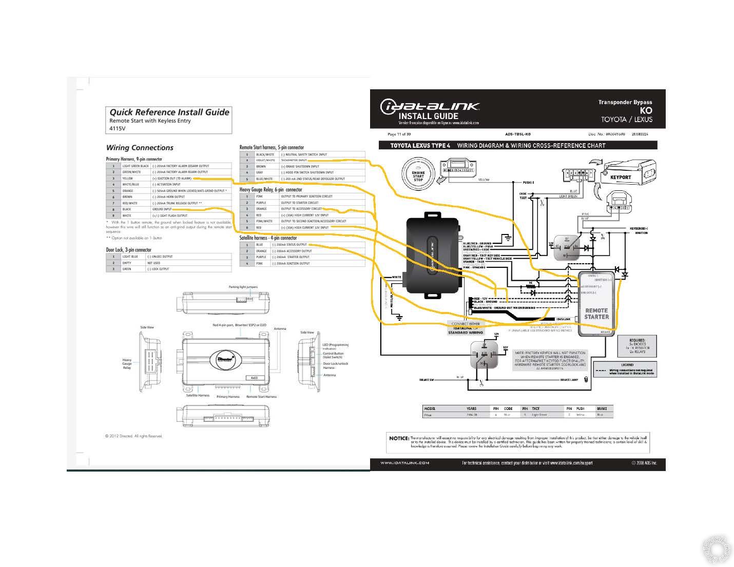
Hello I need a little input from you all please. I am wiring up a viper 4115 into my 08 prius. I have done a lot of research and know a majority of the complications that come with putting a remote start on this car but I am attempting it. The snag I ran up at this point though is trying to figure out 1 wire coming off of the viper unit to the IDSL KO bypass unit. In the pics you can see the highlighted one with the yellow arrow pointing to it calls for an accessory +. I can not find an accessory + coming off of this unit (wiring diagram also attached). Can you all point me in the right direction on making this happen please. Thanks in advance, Dale 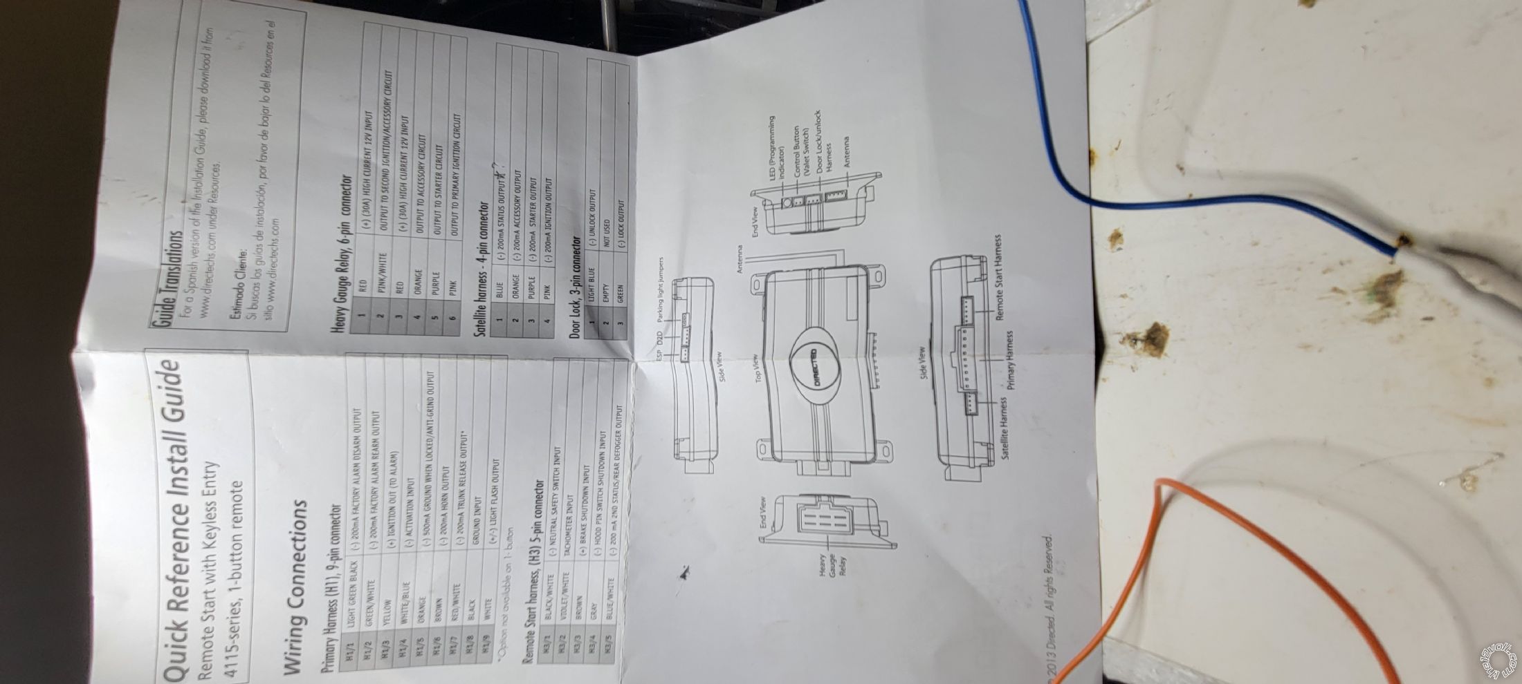 
Replies:
Posted By: kreg357
Date Posted: December 08, 2023 at 8:55 PM
A few things to point out...
The Viper 4115 uses DBI D2D communications at the 4 Pin Data port. You should flash the ADS-TB module with the DBI-TB-TL flavor of firmware and follow Install Guide #77711, Type 4.
If you have the older Solo Series ADS-TBSL-KO bypass module, then it will not go D2D with the Viper 4115 and you must install using the W2W method.
The ACC(+) wire you need is the thick Orange wire at the 6 Pin Plug.
-------------
Soldering is fun!
Posted By: dacker
Date Posted: December 11, 2023 at 5:44 PM
Great and yes it is the older one do I will use the heavy gauge wire for that connection. Thank you for the reply and I'm sure I'll have more questions.
Posted By: kreg357
Date Posted: December 11, 2023 at 6:32 PM
Yes, use the thick Orange ACC wire at the Viper 4115.
In W2W mode all of the dashed black lines have to be connected as shown.
The diodes are 1N4001's. You can also use similar diodes like the 1N4007, etc. Just be sure to get the band going the correct way.
-------------
Soldering is fun!
Posted By: dacker
Date Posted: December 20, 2023 at 10:29 AM
I am still struggling with this thing. I got everything hooked up this weekend, and I have power and the LED light working on the Idatalink, but the 4115 remote box seems to be doing nothing. I hear no clicking, and the LED light never illuminates in any fashion. Here is a drawing of the connections I made. Can you all look at it and tell me what I have hooked up wrong or what else I need to hook up, please?
Posted By: kreg357
Date Posted: December 20, 2023 at 1:34 PM
The iDatalink install guide is a bit generic due to the fact that it can be connected to many different brands and models of R/S systems. Foillow thw install guide and here are the connections the Viper 4115 needs...
4115
Primary Harness, 9-pin connector
1 LIGHT GREEN BLACK (-) 200mA FACTORY ALARM DISARM OUTPUT..............N.U.
2 GREEN/WHITE (-) 200mA FACTORY ALARM REARM OUTPUT............................N.U.
3 YELLOW (+) IGNITION OUT (TO ALARM).....................................................................N.U.
4 WHITE/BLUE (-) ACTIVATION INPUT............................................................................N.U.
5 ORANGE (-) 500mA GROUND WHEN LOCKED/ANTI-GRIND OUTPUT ...............N.U.
6 BROWN (-) 200mA HORN OUTPUT................................................................................Optional ORANGE (-) @ STEERING COLUMN
7 RED/WHITE (-) 200mA TRUNK RELEASE OUTPUT ..................................................Optional PINK (-) @ DKP, 22 PIN CONN., PIN 17
8 BLACK GROUND INPUT...................................................................................................Chassis Ground
9 WHITE (+/-) LIGHT FLASH OUTPUT ...........................................................................BROWN @ FUSE BOX, TOP LEFT CONN., PIN 10 *
* Set Jumper to +
Remote Start harness, 5-pin connector
1 BLACK/WHITE (-) NEUTRAL SAFETY SWITCH INPUT.............................................Chassis Ground
2 VIOLET/WHITE TACHOMETER INPUT.........................................................................as per iDatalink diagram (Orange wire)
3 BROWN (+) BRAKE SHUTDOWN INPUT......................................................................as per iDatalink diagram
4 GRAY (-) HOOD PIN SWITCH SHUTDOWN INPUT....................................................TO Viper Kit Hood Pin
5 BLUE/WHITE (-) 200 mA 2ND STATUS/REAR DEFOGGER OUTPUT...................to bypass module Blue/White
Heavy Gauge Relay, 6-pin connector
1 PINK OUTPUT TO PRIMARY IGNITION CIRCUIT......................................................as per iDatalink diagram
2 PURPLE OUTPUT TO STARTER CIRCUIT..................................................................N.U.
3 ORANGE OUTPUT TO ACCESSORY CIRCUIT...........................................................as per iDatalink diagram
4 RED (+) (30A) HIGH CURRENT 12V INPUT.................................................................to suitable vehicle +12V constant source
5 PINK/WHITE OUTPUT TO SECOND IGNITION/ACCESSORY CIRCUIT..................N.U.
6 RED (+) (30A) HIGH CURRENT 12V INPUT..................................................................to suitable vehicle +12V constant source
Satellite harness - 4-pin connector
1 BLUE (-) 200mA STATUS OUTPUT...............................................................N.U.
2 ORANGE (-) 200mA ACCESSORY OUTPUT...............................................N.U.
3 PURPLE (-) 200mA STARTER OUTPUT.......................................................N.U.
4 PINK (-) 200mA IGNITION OUTPUT...............................................................N.U.
Door Lock, 3-pin connector
1 LIGHT BLUE (-) UNLOCK OUTPUT ..............................................................as per iDatalink diagram
2 EMPTY NOT USED
3 GREEN (-) LOCK OUTPUT .............................................................................BLUE (-) @ DKP, BLUE CONN., PIN 14
-------------
Soldering is fun!
Posted By: dacker
Date Posted: December 21, 2023 at 12:50 PM
Awesome I'll give that a try thank you
Posted By: dacker
Date Posted: December 23, 2023 at 10:47 PM
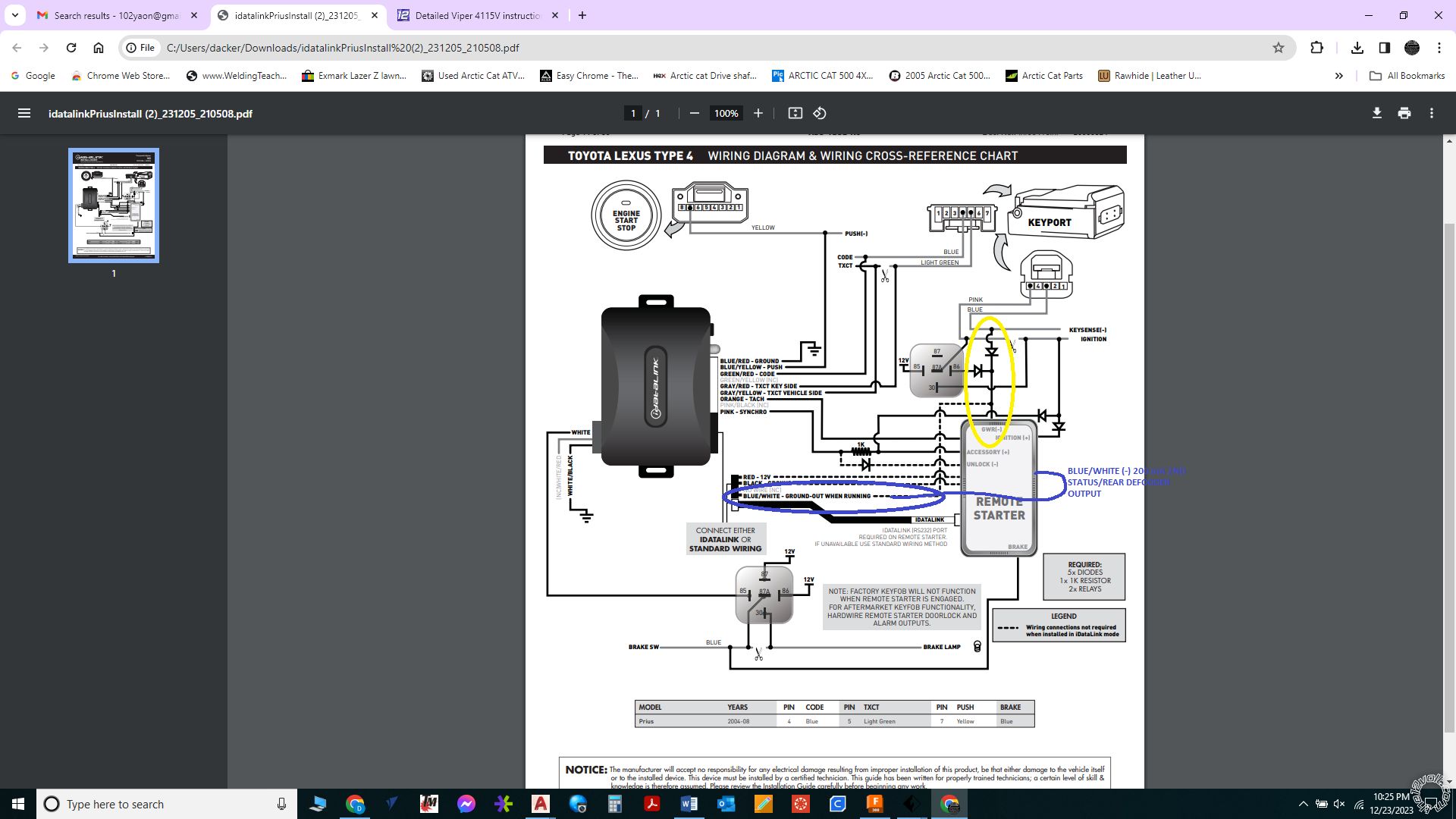
Ok I am getting closer. I made the wiring changes according to what you sent. Now here is what happens. I click the remote and the relays click etc.... nothing powers on however if the door is open the beeper starts beeping like the key is in the ignition whether it is or not (it is a proximity system) and when the relays click I get 12v power to the purple wire on the heavy gauge harness which is not used. The blue and yellow push wire (going to the push-to-start button) stays at a constant .015 volts. So something still is not hooked up right apparently. I contacted DEI before I came on here trying to figure this out and they said the GWR wire was the blue wire on the 4 pin harness you said was not used (area circled in yellow) so what do I do with that area and wires that are circled yellow because from what you said the wire they are saying hooks to it goes straight to the defogger wire circled in blue. Here is where the tech told me that as well as pics of the areas in question. I also am getting no led lights on the physical boxes from with the Idata link or the 4115v where as before the idata link led was blinking. I am not sure if that is necessary info or even relevant since it is receiving and sending signal of some type.
Brian (VOXX International)
Dec 6, 2023, 3:07 PM EST
Dale,
DEI term for ground when running is "Status" wire color is BLUE.
Brian
Thank You
Posted By: kreg357
Date Posted: December 24, 2023 at 3:31 AM
Greetings,
First off, it's nice to hear that VOXX is suppling help to individuals on DEI products.
Their info is basically correct and I hate to argue with Tech Support. There are several names used for Ground When Running. The most popular is GWR but DEI used the term (-) Status Output. Other brands used the term 3rd Ignition, etc.
In your application, using a DEI product with an iDatalink SOLO Series bypass module you must run in W2W Mode between the Viper 4115 and the ADS TBSL KO bypass module. The Viper 4115 only uses their DBI protocol on the 4 Pin D2D port. The ADS TBSL KO only uses their iDatalink protocol on the 4 Pin Data port. So, to control the ADS TBSL KO, the Data style control can't be used and you must wire and run in W2W mode. This is shown in the ADS TBSL KO Install guide as making all the solid and dashed wire line connections.
When installing in the W2W Mode a few things must be done. First, as noted by VOXX Tech Support, the 4115 (-) Status Output signal is used as the GWR signal in the ADS TBSL KO diagram. Typically, most installers will use the Dark Blue wire at Pin 1 of the 4 Pin Satellite Harness. I suggested the use of the Blue/White wire at Pin 5 of the Remote Start harness. I did this because the Remote Start Harness had other wires being used and the Satellite Harness had no other wires needed. Rather than plug in another harness for just one wire, why not keep it simple and use the Blue/White wire for GWR. Please note that the Blue/White wire has two functions*. The Factory Default setting is (-) Status Output (GWR). The optional setting is for Defrost control. This is shown in the 4115 programming, Menu 2, Feature 8. I have used the Blue/White wire for GWR bypass module control many times when I don't need it for Defrost control and it always works. As long as the 4115 Menu 2, Feature 8 setting is still at the Factory Default setting of (-) Status Output ( OPT 1), my suggestion will work.
* Here is a description of these two wires from an older DEI Install Guide :
BLUE/WHITE (-) 200mA 2nd Status/defroster output
This wire supplies a 200mA output as soon as the module begins the remote start
process. This BLUE/WHITE wire can also be used to activate the defogger trigger
(latched/pulsed) 10-seconds after the remote start engages. (See the Feature
Descriptions, Menu#2, feature 8 for details about programming this output.)
BLUE (-) 200mA status output
This wire supplies an output as soon as the module begins the remote start process.
It can be used to activate a bypass module or power the key sense wire in
most vehicles to disarm the factory alarm without unlocking.
It's your choice if you wish to add the 4 Pin Satellite Harness and use that Dark Blue GWR signal or use the Blue/White GWR wire.
The other important item that must be done is setting the ADS TBSL KO to Standard Mode. This tells the bypass module that it is not using the 4 Pin port for Data style communication and that its Blue/White wire will have only the GWR signal on it. I can't obtain the older version guide #415 that you are using but at the end of that Toyota wiring section, the install guide has a Programming Section. Typically at the top of the Programming Section are Installation Mode Selection setting. You must tell the ADS TBSL KO that it is to run in Standard Mode ( 2 Blinks ) and lock it down prior to doing the Vehicle Programming steps. In the later guide I found for the ADS TBSL KO, you use the specific Type 4 vehicle programming after setting the Install Mode to Standard. At this point, I would recommend doing a Factory Reset on the bypass module. This is shown at the end of the Install Guide. Please note that at Step 5, after the Red LED goes out, it will start doing a 1 Blink pattern for DATA Mode. If you press the button once the LED will start doing a 2 Blink pattern for Standard Mode. At this point you can press and hold the button to lock in Standard Mode. Then continue to Type 4 vehicle programming.
This is a rather involved install with relays, plenty of diodes and a resistor. There are many areas for possible problems. I would also verify that all diodes are oriented correctly.
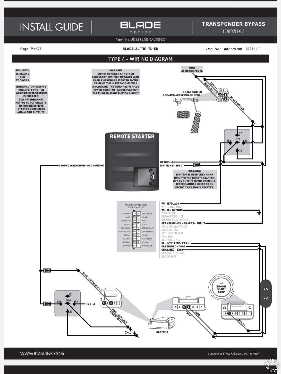
As for the Vipers Purple Starter output wire, here is a note added to the later Type 4 install guide :
WARNING
DO NOT CONNECT ANY OTHER ACCESSORY, IGNITION OR START WIRE FROM THE REMOTE STARTER TO THE VEHICLE. THE INTERFACE MODULE IS HANDLING THE REQUIRED VEHICLE POWER AND START SEQUENCE FROM THE PUSH TO START BUTTON CIRCUIT.
Good luck,
Kreg
-------------
Soldering is fun!
Posted By: dacker
Date Posted: December 24, 2023 at 7:26 PM
I finally got it!!!! Remote start is working flawless every time. I had one of the wires landed on the wrong relay this whole time. Great job I know lol. Only thing I have left to figure out is why my keyless entry isn't working when the remote start is active. I have to use the physical key to unlock the door and take the car over. I am sure it is something else dumb I have done but hey it is way farther than where I was to begin with. Kreg357 I can't say thank you enough for all your help and detailed responses. People like you are what makes forums like this such a good resource for people who don't do this type stuff all the time. Again thank you my friend.
Posted By: kreg357
Date Posted: December 24, 2023 at 8:28 PM
Happy to assist and glad it's working.
It is normal for a Toyota to turn off the RKE while the engine is running. I always use 4 button RS systems on these type installs. Anyway, the older install guide you are using does not show the wiring for the R/S Unlock wire. The newer ADS TBSL KO install guide does. Here is a link to that guide :
https://images2.idatalink.com/corporate/Content/Manuals/TB-KO/ADS-TBSL-KO-EN_20131003.pdf
Go to Page 65 for the wiring for your car.
I'm not positive that it will work. There could have been a firmware change but if the rest of the wiring is the same you could try adding the shown diode and Unlock wire to this vehicle wire :
Unlock PINK (-) DKP, BLUE CONNECTOR, PIN 13
The above wire should be right next to the Lock wire posted in my 4115 wire connections. Adding this diode and wire should give you Unlock from the Viper remote.
With a one button Viper 4115 system the Unlock function will only work while the engine is remote started. There is no ability to lock the car from the Viper remote.
Enjoy,
Kreg
-------------
Soldering is fun!
Posted By: dacker
Date Posted: December 25, 2023 at 5:12 PM
Gotcha I'll give it a shot. Appreciate you again my friend.
Posted By: dacker
Date Posted: December 26, 2023 at 11:17 PM
I'll repost my results when I get time to add the other diode for the door locks but I did come up with another question. My daughter wants me to do hers now (shocker lol). So I get to looking for the idatalink ads tbsl ko and it's pretty tough to find. Is there another (maybe even better) transponder you would recommend? Thanks in advance
Posted By: kreg357
Date Posted: December 27, 2023 at 12:01 AM
What year, make and model car does your daughter have?
-------------
Soldering is fun!
Posted By: dacker
Date Posted: December 27, 2023 at 8:24 AM
Hers is an 05 Prius so same as mine. I think they're the same from 04 to 09.
Posted By: kreg357
Date Posted: December 27, 2023 at 9:04 AM
Yes, 2004 thru 2010 are similar.
I would go with a Compustar CS925 remote start unit with a Blade TB bypass cartridge. There is an EBay seller that has this system listed and will flash the Blade TB with the correct (TL) firmware prior to shipment. Install will be similar and the two 4 Button remotes will provide RKE, including while running.
-------------
Soldering is fun!
Posted By: dacker
Date Posted: December 29, 2023 at 4:44 PM
Sounds good I will check that out. Thank you
Posted By: dacker
Date Posted: January 03, 2024 at 4:14 PM
I got around to trying the diode last night and there was still no response from the rke while the remote start was engaged. It seemed like in my year of research before I attempted the install I read where someone figured out how to make it work but can't find it for the life of me. Got any more ideas?
Posted By: kreg357
Date Posted: January 04, 2024 at 9:13 AM
Interesting. I'm pretty sure it should work. Just to verify your wiring, below is a clip from your older ADS TBSL-KO install guide and the added Unlock wire with diode.

The connection point and the diode orientation is critical. You can test the vehicle wire with a Digital Multi Meter. Set to 20V DC, Red test lead to +12V constant and the Black test lead to the vehicles Pink Unlock wire. Insert the key into the drivers door lock cylinder and turn to Unlock. The DMM should go to +12V.
The other important thing is that the 4115 can/will output the Unlock signal only while the engine is running under a R/S. Additionally, you should set the 4115 to output a "Double Unlock Pulse" by setting the Menu 1 Feature 5 to Option 2. You can test the Vipers Unlock output (while R/S running) using the DMM and the same setup ( Black Lead to Pink wire). You will see the DMM go to +12V for about .6 seconds and then again for another .6 seconds.
That should do it. ------------- Soldering is fun!
Posted By: dacker
Date Posted: January 07, 2024 at 7:19 PM
100% working unlock and all now. Again I can't begin to tell you how much help you have been through all of this. Hopefully one day I can pay you back don't
Somehow my friend.I just ordered the other set up you mentioned from eBay to do my daughter's car. Are the set up instructions for it on idatalink website or do you have a better set of them like you walked me through here?
Posted By: dacker
Date Posted: January 07, 2024 at 7:22 PM
And to answer your initial question yes that is the way it was hooked up. Initially I don't think I had a good connection somewhere with the diode add in.
Posted By: kreg357
Date Posted: January 08, 2024 at 2:58 PM
The EBay seller should have flashed the Blade-TB cartridge with the latest version of ADS-TB TL firmware. The current Install Guide is #77702. Follow the Type 4 diagram. Here is a link to the install guide : https://images.idatalink.com/corporate/Content/Manuals/TB-TL/BLADE-TB-TL-EN_20211111.pdf
Remember that the guide is somewhat generic with regards to the R/S controller. There will be several wires that need to be connected from the R/S to the vehicle but are not shown. These include the 2 thick Red fused +12V power input wires, the Black Chassis Ground wire, the Parking Lights, the 2 lock wires, the Hood Pin and optional Horn. Overall, this install will be very similar to the previous one. As noted, you will need 2 relays and 3 1N4001 diodes.
-------------
Soldering is fun!
Posted By: dacker
Date Posted: January 20, 2024 at 11:48 PM
Ok I ordered this unit for my daughter's car. Hooked everything up according to the diagram (same as the one you posted) I also hooked both 12v fused constants up red and red/white and the black ground from the CN1 harness. I have ground while running wire hooked to the CN3 (gray) #4 black wire And this thing will do absolutely nothing. I even put a test light on the blue unlock (negative) signal wire to see if it was even giving any type signal and it wasn't. Any ideas what I'm doing wrong here. I did do the reset procedure (pull cartridge out hold button down while reinstalling cartridge then let the button go) and I hope I didn't screw something up. When I do that the led will just blink about every 3 seconds with still no kind of response from the unit otherwise. Only other thing that puzzled me was I did blow the brake light fuse 2 times and I'm not sure how that happened but I chalked it up to be grounding something out moving wires around or whatever. I guess my biggest question is there other wires that should be hooked up besides the one on the diagram, and the 3 others I mentioned to make the RS at least have some type of response. I realize I need to hook the lights, locks, horn etc up for them to function but in my mind the actual start part of it should be working at this point unless another wire needs to be hooked up that I'm missing. Thanks in advance for you help.
Posted By: kreg357
Date Posted: January 21, 2024 at 8:10 AM
OK, CM925 with Blade-TB flashed with the ADS Blade TL firmware. Using the #77702 Install Guide and its' Type 4 wiring diagram.
With blowing the vehicles' Brake fuse, you definitely want to check the relay and wiring. Brake pedal connector Pin 2 should be Black and show +12V. Brake pedal connector Pin 1 should be Blue and show +12V when the pedal is depressed.
If the wires are soldered and insulated, moving thigs around shouldn't blow fuses.
A factory reset won't hurt anything. Did the Blade TB program correctly? If not check the Blade wiring and the thick Green IGN1 w/diode wiring.
Wring below :
CM900-s
CN1
Pin 1 Red - Constant 12V .........................................joined with Red/White, fused down & to 12V Constant source
Pin 2 Green/White - Programmable Output.............BROWN @ FUSE BOX, TOP LEFT CONN., PIN 10
Pin 3 Red/White - Constant 12V................................joined with Red, fused down & to 12V Constant source
Pin 4 White - Accessory 12V positive (+).................Not Used
Pin 5 Blue - Programmable Output...........................Not Used
Pin 6 Yellow - Starter 12V positive (+)......................Not Used
Pin 7 Green - Ignition 12V positive (+).....................As per diagram w/1N4001 diode
Pin 8 Black - Ground negative (-) input....................Chassis Ground with Blade connector White wire
CN3
Pin 1 Green/White - (fixed) Parking light (-) output............................................Not Used
Pin 2 Blue/Lt. Green - [POC 2] Lock 250mA, 800mS (-) output.......................BLUE (-) @ DKP, BLUE CONN., PIN 14
Pin 3 Blue - [POC 3] Unlock 250mA, 800mS (-) negative output.....................PINK (-) @ DKP, BLUE CONN., PIN 13
Pin 4 Black - [POC 4] (GWR) 250mA latched (-) output...................................As per Type 4 diagram w/1N4001 diodes and relay
Pin 5 Orange - [POC 5] Factory Alarm Arm (FAA) (-) output............................Not Used
Pin 6 Orange/White - [POC 6] Factory Alarm Disarm, 800mS (-) output........Not Used
Pin 7 White - [POC 7] Horn:250mA negative (-) output.....................................ORANGE (-) AT STEERING COLUMN (optional)
Pin 8 Gray/Black - Hood Pin negative (-) input...................................................to kit supplied Hood Pin
Pin 9 Light Blue/White - Brake 12V positive (+) input........................................As per Type 4 diagram
Pin 10 RED/White - Trigger start (-) input........................................................... Not Used
Pin 11 RED - Positive Trigger (+) input.................................................................Not Used
Pin 12 Yellow/Black - Engine sensing input (A/C)...............................................Not Used
Blade 20 Pin connector as per diagram.
Connect CM900 antenna harness and antenna.
At this point the Compustar remotes should work the car locks.
Questions :
1. With everything connected, do the Parking Lights flash with a Lock or Unlock from the Compustar remotes? *
1a. If NO, do you hear any clicking from the CM900 controller? **
2. Did the Blade cartridge program properly as per the Type 4 programming on Page 23? **
3. Do the Brake lights come on with a R/S attempt?
* check antenna connection and for blue LED flash on remotes
** check CM900 power and ground connections.
** check Blade connector wiring
You might have to program CM900 Menu 2, Feature 10 to Option 4 for a Hybred install.
-------------
Soldering is fun!
Posted By: dacker
Date Posted: January 21, 2024 at 8:11 AM
Sorry I forgot to link the unit. Here you go.
https://www./itm/334289133079?mkcid=16&mkevt=1&mkrid=711-127632-2357-0&ssspo=VdmfqXDXTI-&sssrc=4429486&ssuid=i1OBUVAsRju&var=&widget_ver=artemis&media=COPY
Posted By: dacker
Date Posted: January 21, 2024 at 8:15 AM
And just saw your reply. I will do all that today and let you know. Thanks
Posted By: kreg357
Date Posted: January 21, 2024 at 8:24 AM
Did the seller include anything concerning the Blade-TB firmware flash?
-------------
Soldering is fun!
Posted By: dacker
Date Posted: January 21, 2024 at 8:00 PM
Just this email is there something else specific I can look for?

Posted By: kreg357
Date Posted: January 21, 2024 at 8:24 PM
Not really, just wanted confirmation that the cartridge was flashed with the correct firmware and they made reference to the proper install guide to use.
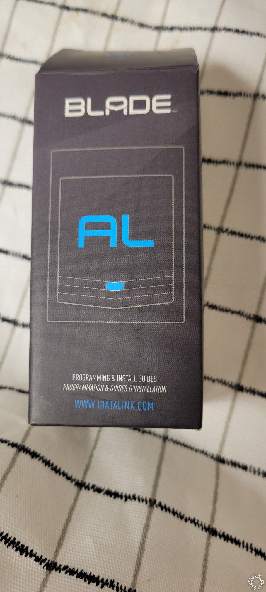
Just making sure we are looking/using the same Blade-TB-TL install guide. A little confusing as they say "Blade-AL" instead of Blade-TB but no big issue as the module only handles the R/S and transponder bypass but no convenience features.
Any issues found?
-------------
Soldering is fun!
Posted By: dacker
Date Posted: January 21, 2024 at 10:30 PM
Just this email is there something else specific I can look for?
Posted By: dacker
Date Posted: January 21, 2024 at 10:40 PM
Apparently it is an al here was the box it came in
Posted By: dacker
Date Posted: January 21, 2024 at 10:49 PM
This was the install guide I used
Posted By: kreg357
Date Posted: January 22, 2024 at 7:45 AM
While they used the more expensive Blade-AL cartridge, the functionality and wiring is the same.
I'm not really sure where you are right now.
Do you have all the wiring as per the Type 4 diagram and my CM900 posted list?
Did all of the vehicle wire colors and locations match?
Does the vehicle still start and operate normally?
Did the Blade program exactly as per the install guide Type 4 steps?
Do the Compustar remotes control the door locks and flash the parking lights?
Did you change the 2-10 option to 4?
Does pressing and holding the R/S button 3 seconds do anything (Brake lights should come ON)?
-------------
Soldering is fun!
Posted By: dacker
Date Posted: January 22, 2024 at 10:32 PM
Hey sorry for the delay I got slammed with another work issue but I got around to checking everything and here is where I am.
Do you have all the wiring as per the Type 4 diagram and my CM900 posted list? Yes except for Pin 2 Green/White - Programmable Output.............BROWN @ FUSE BOX, TOP LEFT CONN., PIN 10 I am not sure how to get to this and the fuse box runs parallel to the ground so I am not sure what exactly I am looking for or hooking up.
Did all of the vehicle wire colors and locations match? Yes
Does the vehicle still start and operate normally? Yes, if you are referring to me putting the key in the slot and foot on the brake and pushing the PTS button.
Did the Blade program exactly as per the install guide Type 4 steps? Yes
Do the Compustar remotes control the door locks and flash the parking lights? No and I think I read on your post where it said parking lights were not used. When trying to control the locks with the computer remote the brain box does click and send a () signal to either the lock or unlock wire whichever button I have hit but the locks do not lock or unlock.
Did you change the 2-10 option to 4? No because I am limited to only the 1st 4 options in the menu without the op500 the best I can tell
Does pressing and holding the R/S button 3 seconds do anything (Brake lights should come ON)? Brake lights do not come on and the led flashes blue 3 times the MFD powers up and I hear clicking from the RS and the led turns red for a second and the just blinks blue 3 times and stops then blinks blue 3 times and stops and so on. It will then click again led turn red and cycle repeats itself. If I do this with the door open when I hold the RS button for 3 seconds and the led blinks blue 3 times the car beeper starts immediately beeping like it will do if you leave the key in the ignition and open the door to get out so to remind you not to leave the key in the slot.
I also checked the wire at the PTS button and it gets a negative pulse when trying to start the car just like if you were pushing the button manually but it never powers on. I double checked all the diodes were facing the correct direction as well and they are.
Posted By: kreg357
Date Posted: January 23, 2024 at 5:56 PM
Thanks for the update.
The fact that the Parking Light wire is not hooked up is not causing any problems. It would provide a nice visual indication of functions and possible error codes. The clicking you hear is the controllers internal (+) Parking Light relay so the remotes are paired and functional. I would double check the vehicle lock wires. I think I described the test procedure during the 2010 Prius install using a DMM and the drivers door key lock cylinder. You will need to set the CM900 to a double Unlock pulse (1-4 Option 2).
The fact that the car is still operational with a regular start-up is good news.
It also appears that the Blade cartridge programmed properly.
It is possible to change CM900 options using the remotes. The two Special Option Groups can only be changed with the OP-500 Programmer but the other 4 Groups can be changed with the remotes. It requires a bit of effort as timing is critical. The full CM900 Install Guide is in the Downloads section of this site.
The instructions for your 4 button 1 way remotes are at the bottom of Page 47. Use the tables included with the you system as some options have changed /enhanced. The two you should change are the same.
I'm pretty sure the Brake lights should come on during a R/S attempt. You should check those connections/relay to ensure all is correct. Basically, the White wire of the 20 Pin Blade plug has Chassis Ground. When the Blade cartridge see a R/S request it outputs that Chassis Ground signal on the White/Black wire. This turns on the "Brake Relay" and connects Pin 87 to Pin 30. Pin 87 has +12V on it and this 12V gets output on Pin 30. Pin 30 is connected to the vehicle Brake wire simulating a Brake Pedal press. The relay wiring also prevents the CM900 from seeing the +12V on the Brake wire which would prevent or shutdown a R/S.
-------------
Soldering is fun!
Posted By: dacker
Date Posted: January 24, 2024 at 9:32 PM
You got to love electronics. Somehow the white #9 ground pin off the blade plug had gotten pushed back out of the connector and wasn't making a connection this whole time 🙄. We are 100% now locks, lights, start and all. Again Kreg357 you are a true lifesaver I couldn't have done either of these without you my friend!!!!
Posted By: kreg357
Date Posted: January 24, 2024 at 9:55 PM
Great news! Thanks for the update. Enjoy your hard work with a warm car!
-------------
Soldering is fun!
|