Viper ESP550 Trunk Output
Printed From: the12volt.com
Forum Name: Car Security and Convenience
Forum Discription: Car Alarms, Keyless Entries, Remote Starters, Immobilizer Bypasses, Sensors, Door Locks, Window Modules, Heated Mirrors, Heated Seats, etc.
URL: https://www.the12volt.com/installbay/forum_posts.asp?tid=39446
Printed Date: May 18, 2024 at 1:43 PM
Topic: Viper ESP550 Trunk Output
Posted By: fierygt
Subject: Viper ESP550 Trunk Output
Date Posted: September 20, 2004 at 7:59 PM
Hey guys, new to this forum, so please forgive me, but have a few years experience in this genre. Ok, so anyway, i think i may have messed the trunk output of the Viper 550 alarm, because i was replacing the relay that controls that part of the unit, and not paying attention i hooked up the relay wrong. Before you ask how, basically i guess i was just off by one connection when i rehooked it back up. I was mainly wondering if anyone here is good with the internals of these types of electronics and if they could give some advice. Seems like I may have messed up a resistor or maybe transistor inside the control unit. The unit is still sending a signal to that relay though, so i am right now kind of flustered. Any advice anyone?
Replies:
Posted By: Teken
Date Posted: September 20, 2004 at 8:02 PM
What is the current output from the alarm CPU? Less than 100 mA?
Regards
EVIL Teken . . .
Posted By: fierygt
Date Posted: September 20, 2004 at 8:16 PM
hey teken, the manual says the output can only supply 200mA of current, does that help you?
Posted By: Teken
Date Posted: September 20, 2004 at 8:30 PM
I'm sorry that wasnt what I asked you. Please take your DMM and configure it to measure (I) current.
Once you activate the trunk out put, you should be able to measure the current output coming out of the alarm CPU.
The current output from the alarm needs to be above 100 mA.
There are only a few relays that can sustain a open / close contact with a *holding current* of less than 100 mA based on a standard Bosch, P&B, or Midtex relay.
Measure it, and let us know, it could be the output.
Regards
EVIL Teken . . .
Posted By: fierygt
Date Posted: September 20, 2004 at 8:54 PM
ok Teken, just measured, and here are the figures i got. Bear in mind my digital multimeter is pretty crude, but i'll give you a couple of different readings. If I set the multimeter to 2000m, I get a reading of about 617(constant), now if i set it to 20 volts i get a reading of .62 volts. I am not very good at translating measurements but both sound adequate to me. Like i said, my multimeter isn't very sophisticated but will those readings work ok for you? I am going to work on translating them right now to make sure, there adequate, but i also want to thank you for the help so far and i'll wait for a reply.
Posted By: fierygt
Date Posted: September 20, 2004 at 9:11 PM
Teken, sorry, but please disregard that whole last post, as i measured in volts. Sorry about that. If i measure with the dmm set at 20mA, i get a reading of 1.30, if i set it to 200mA, i get a reading of 1.3 so does that make any sense to you. Sorry about the confusion, as i am still learning my electronics skills.
Posted By: Teken
Date Posted: September 20, 2004 at 9:13 PM
If the voltage is indeed 0.62 VDC. The output is none functional.
aka = Output is fried
It needs to be 12 volts, and the output current needs to be at least 65-100 mA. 200 mA is what it should output, but a relay can still function with 65-100 ish.
Regards
EVIL Teken . . .
Posted By: Teken
Date Posted: September 20, 2004 at 9:15 PM
You are doing just fine. When the DMM is at the 20 mA range you are measuring only 1.30 mA?
If so, the output is dead, please have it serviced or replaced.
Regards
EVIL Teken . . .
Posted By: fierygt
Date Posted: September 20, 2004 at 9:26 PM
hey Teken, unfortunately i installed this alarm by myself several years ago, which meant no warranty. And the fact that the trunk output is the only part that doesn't function doesn't really give me enough motivation to get a whole new system. Do you know if it might be a transistor or resistor or maybe even a diode that could need replacing? I don't mind opening it up and trying. I have built some cables and things to relay to my car's ecm so i could hook into a laptop, so i'm not totally ignorant when it comes to those parts, but not sure where to look when something goes wrong. Any more information is greatly appreciated and thanks for all the help so far.
Posted By: Teken
Date Posted: September 20, 2004 at 10:13 PM
I just want to ensure we are both on the same page. When you configured your DMM to measure curent, you have to place the red (+) lead from your DMM in the (mA) milliampere jack, and not in the AMP's jack.
The dial also needs to be adjusted to the correct reading value to capture the current. Start from the highest reading, and work your way down untill you capture a current reading.
As for the voltage, you will again have to plug in your test leads to the appropiate jack for volts, and leave the black lead on the common jack.
Place the DMM in VDC, and not ACV, and measure the reading each time you hit the button on your remote control to intiate the output.
Please let me know if the numbers are correct as they are stated above.
If so, you can simply leave the unit alone, and use the relay diagram to the left of this forum, to make a dual use output channel. It is not the ideal method, but it can be made to work for your application if you wish.
Regards
EVIL Teken . . .
Posted By: fierygt
Date Posted: September 20, 2004 at 11:10 PM
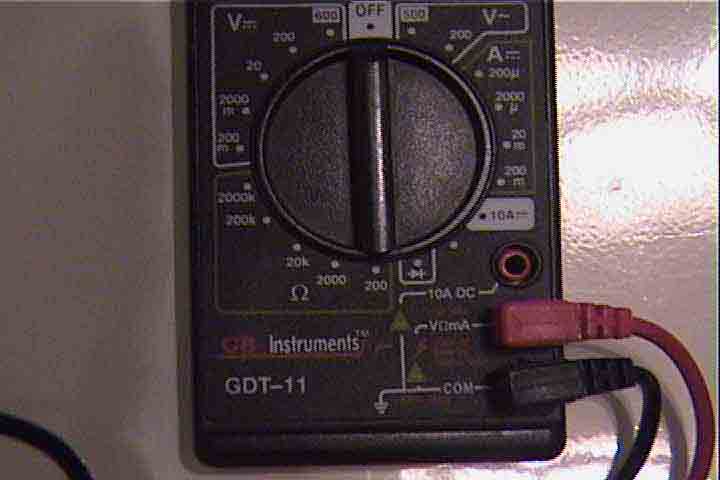
Posted By: fierygt
Date Posted: September 20, 2004 at 11:17 PM
ok teken, i figured i would just show you the multimeter i am using. when i tested, i turned the dial to both the 20m and the 200m, which are on the right side of the unit.(if the picture is bad) That is where i got my 1.3 and 1.30 readings. And the probes are set up exactly as the picture shows. Thanks for the constant help.
Posted By: Teken
Date Posted: September 21, 2004 at 8:31 AM
Interesting, I have not seen a meter use both volts and amps in the same out let before.
GB is a good brand anyways, no worries.
When you set the meter to 200 mA, did the meter show you any reading?
Remember you must place the meter inline (series) with the circuit to measure the current (I).
Just want to make sure this is being done.
If you have to set it to 20 mA to obtain a reading, then yes the output is dead.
Follow up with a voltage measurement as well, and let us know what the voltage is coming out of the unit, when you depress the key fob.
Regards
EVIL Teken . . .
Posted By: fierygt
Date Posted: September 21, 2004 at 11:35 AM
Teken forgive me, but not sure what you mean when you say "Remember you must place the meter inline (series) with the circuit to measure the current (I). "
Posted By: Teken
Date Posted: September 21, 2004 at 4:23 PM
When measuring voltage you are placing the meters leads in parallel to the point to be measured.
When current is being measured, you must break the circuit which is under test. And place the DMM leads in series with the circuit.
ie. Alarm CPU outout ---> Neg (-) DMM cable ---> Pos (+) DMM cable to the relay in question.
One side of the DMM will be attached to the output of the alarm trunk output wire, the other end of the DMM lead will attach to the other wire leading to the relay.
Hope that clarify it for you, if not, I will try to rephrase it for you.
Regards
EVIL Teken . . .
Posted By: fierygt
Date Posted: September 21, 2004 at 4:55 PM
Hey Teken, I got what you mean now. Anyway here are the readings... If multimeter is set to 20mA, I get reading of 1.25 If multimeter is set to 200mA, I get reading of 01.3 Now, on the voltage side, if i set multimeter to 20Volts, I get reading of 0.60 If multimeter is set to 2000m, on voltage side, i get reading of 587... Now here's an interesting one which i'm not sure of...On the right side of the multimeter, where the ampere settings are, there is one called 2000u, which the reading on that one is 1190. So can you help me translate these numbers and tell me what might be next? Thanks Again
Posted By: mito57
Date Posted: September 21, 2004 at 5:25 PM
The "u" is really the greek letter for "m" and stands for "micro". So if your range is 2000 u that means a full scale of 2,000 divided 1,000,000. That is a maximum reading of .001190 Amp if you are reading 1190, which is equivalent to a reading of 1.19 in the 20mA scale.
Posted By: kgerry
Date Posted: September 21, 2004 at 6:44 PM
the aux channel is smoked...... you can replace the transsitor inside or ship it in to be serviced....
-------------
Kevin Gerry
Certified Electronics Technician
MECP First Class Installer
Owner/Installer
Classic Car Audio
since 1979
Posted By: fierygt
Date Posted: September 21, 2004 at 6:50 PM
hey kgerry do you happen to know how to locate the correct transistor in the unit? Thanks for the replies everyone.
Posted By: fierygt
Date Posted: September 24, 2004 at 8:50 PM
hey all. problem fixed! Problem was a resistor located at the trunk output terminal. Replaced with a 10ohm(What the unit calls for)and now it works perfectly! Consider this topic closed.
Posted By: JWorm
Date Posted: September 24, 2004 at 11:21 PM
My first time reading this topic...
I believe the Viper 550 has another aux. channel that is violet/black. Its located in a 3 pin purple plug at the brain. I rarely used that harness, since those wires were rarely needed. You could have used that for your trunk release....assuming you weren't using it for something else.
|