2000 Chevy Venture Remote Starter
Printed From: the12volt.com
Forum Name: Car Security and Convenience
Forum Discription: Car Alarms, Keyless Entries, Remote Starters, Immobilizer Bypasses, Sensors, Door Locks, Window Modules, Heated Mirrors, Heated Seats, etc.
URL: https://www.the12volt.com/installbay/forum_posts.asp?tid=64994
Printed Date: May 23, 2024 at 9:09 AM
Topic: 2000 Chevy Venture Remote Starter
Posted By: campuschill
Subject: 2000 Chevy Venture Remote Starter
Date Posted: October 25, 2005 at 4:49 PM
I am trying to install a Code-Alarm CSI 400 remote starter system in a 2000 Chevy Venture, with a DEI 555G Passkey III bypass. I would like to know if i need the SPDT relays for this installation. I will appreciate any help. Thanks
Replies:
Posted By: mo12v
Date Posted: October 25, 2005 at 5:34 PM
That depends on what you need them for..???? | Constant 12 volts | RED & RED / WHITE | IGNITION SWITCH HARNESS * | | Ignition 12 volts | PINK | IGNITION SWITCH HARNESS | | Starter | YELLOW | IGNITION SWITCH HARNESS | | Dome Light | GRAY/BLACK (-) | AT BULK HEAD CONN.UNDER DRIVERS DASH | | Trunk Pin Switch | GRAY/BLACK (-) | SAME AS DOME LIGHT WIRE ABOVE | | Parking Lamp | BROWN (+) | AT HEADLIGHT SWITCH *** | | Power Lock | L BLUE | 10 PIN CONNECTOR IN | | Power Unlock | WHITE | DRIVER KICK PANEL |
* Separate Circuits - RED Fused At 60 And RED / WHITE Fused At 40 Amps. ** Alternate Door Trigger Circuit: TAN (Dr), D BLUE (Ps Front And Liftgate) And ORANGE (Sliding Door) (-) At Body Control Module Below Passenger Dash. Diode Isolation Needed, Cathode (Band) Side Of Diode Faces OEM Wires. *** BROWN (+) Wire Also Located In 56 Pin Conn. Near Driver Kick Panel. Negative Pulse Door Locks | Accessories | | Window Up | D\ D BLUE P\ L BLUE @ MAIN SWITCH | | | Window Down | R/ BROWN S/ TAN | | | Ign Key Warn | L GREEN (-) | 48 PIN CONN. AT BASE OF STEERING COL. | | Trunk Release | N/A | | | OEM Horn | BLACK (-) | STEERING COLUMN HARNESS | | Headlights | YELLOW (+) | AT HEADLIGHT SWITCH * | | OEM Alarm Arm | RED / BLACK (-) | | | OEM Alarm Disarm | ORANGE / BLACK (-) | IN DRIVERS KICK PANEL |
Reversal Rest At Ground Power Window Circuit Diagram.
* YELLOW (+) Wire Also Located In 48 Pin Black Connector At Base Of Steering Column. ** OEM Alarm Arms By Locking Doors Thru OEM Keyless Entry Transmitter Or By Locking Doors Using Inside Door Lock Switch While Driver Door Is Open. | Remote Start | | Tach Signal | WHITE | AT POWERTRAIN CONTROL MODULE * | | Ignition #2 | ORANGE | IGNITION SWITCH HARNESS (HEAT/AC) | | Ignition #3 | WHITE | IGN. SW. HARN. (INSTRUMENT CLUSTER) | | Accessory | BROWN | IGNITION SWITCH HARNESS | | Neutral Safety | NOT GROUNDING TYPE - | OEM SWITCH OPENS STARTER CIRCUIT | | Brake Light | WHITE (+) | AT SWITCH ABOVE BRAKE PEDAL | | Reverse Light | L GREEN (+) | 56 PIN CONN. TO LEFT OF STEER. COL. | | Rear Window Defrost | N/A | TIMER BUILT INTO SWITCH |
* Powertrain Control Module Located On Driver Front Of Engine In Air Cleaner Housing.
Immobilizer Bypass ------------- MO
Don't Learn from Others Mistakes
You Might Be the One That Knows.
Posted By: campuschill
Date Posted: October 25, 2005 at 5:49 PM
MO,
Thanks for your response. I did not understand your question. I would like to start the van with the RS system and have it warm and also the rear defogger ON. I have OEM keyless entry in the VAN. Please advice.
Posted By: gus1
Date Posted: October 25, 2005 at 5:49 PM
No you will not, however, the 555G will "hang" the security light when you take over with the key. It's nothing that you did, it is a software issue in the 555G.
Gus
PS- PKG-5 works a lot better!
-------------
Wherever I go, that is where I end up......
Posted By: campuschill
Date Posted: October 25, 2005 at 6:00 PM
Thanks Gus.
Which is the security light? What is PS-PKG-5?
Also in-case i want to use the keyless entry system from the CSI-400 instead of the OEM, would i need the relays or any additional components.
Posted By: gus1
Date Posted: October 25, 2005 at 6:07 PM
The security light is the one that says "security" in the dash....
And, no, you do not any relays (already answered that)
PS- Post script.
It is just PKG-5 from either Automobility or Bypasskits.....
Gus
-------------
Wherever I go, that is where I end up......
Posted By: mo12v
Date Posted: October 25, 2005 at 6:16 PM
Also OMEGA | GM Passkey 3 & Passlock 2 Override Interface (DB-PASS-23A) |  |  | |
|
| GM Passkey Transponder Bypass: Grand Prix 2004 (IB-UGM) | | |
------------- MO
Don't Learn from Others Mistakes
You Might Be the One That Knows.
Posted By: campuschill
Date Posted: November 02, 2005 at 5:12 PM
I am going to install the RS tomorrow. Meanwhile a friend tells me that it would be better if i disable the airbag system before i start this work. He feels that i might trigger the airbag deployment by mistake. Is there a possibility for this to happen, if yes, is there a way to disable the airbag system temporarily untill i install the RS and how?
Thanks
Posted By: tjdurham
Date Posted: November 02, 2005 at 10:12 PM
DO NOT DISABLE THE AIRBAG""""""" Just stay away from any wires covered in a yellow tubing and use a digital meter to test your wires if your are not sure
-------------
tj
Posted By: Chris Luongo
Date Posted: November 03, 2005 at 6:09 PM
Don't worry about the airbag; just avoid yellow-taped wires as others have said. When you try operating the various functions of the remote for the first time, it would always be wise to be away from the airbag when doing so, just in case.
Does your Venture have a factory alarm? There are two different ways you should do the locks, depending on whether you have an alarm or not.
Open a window. Lock the doors with the factory remote. Leave the car alone for at least 30 seconds. Reach in through the open window and "break into" the car. Do you hear the horn sounding?
Posted By: campuschill
Date Posted: November 04, 2005 at 12:06 PM
Thanks for answering my questions.
Today i started the installation of code alarm of the CSI 400 remote starter. I am in the step of connecting the wire to the tachometer in the Engine compartment, but am unable to locate it. Can somebody help me in locating it.
Also what is a firewall connector and where is it located.
This is the first time am working on this van and doing a self intallation of a RS, so i will appreciate any help. Thanks again.
Posted By: campuschill
Date Posted: November 04, 2005 at 1:45 PM
I found a white wire in the harness as mentioned in the wiring diagram section.
In the code alarm instruction manual to verify that it is the correct wire, it is asked to connect a multimeter to measure AC volts between a constant 12VDC (+ve terminal of multimeter) source and the -Ve terminal of multimeter to tacho wire. The manual says the voltage will increase when the engine is running and the gas pedal is pressed.
I tried the above test, as soon i start the engine the voltage is 1.5 V AC and when i press the gas it goes upto 2.5 V AC or sometimes 3 V AC. If further press the gas pedal it constants about 2 V AC. Is this the right wire..please guide me. Thanks
Posted By: kgerry
Date Posted: November 04, 2005 at 2:00 PM
sounds like it is
-------------
Kevin Gerry
Certified Electronics Technician
MECP First Class Installer
Owner/Installer
Classic Car Audio
since 1979
Posted By: campuschill
Date Posted: November 04, 2005 at 6:31 PM
Thanks Kevin,
However i could not get the system working. The CSI-400 has capability of both RS and also keyless entry, but i wanted only the RS, since i have OEM keyless entry in the minivan. To achieve this, following are the wires i connected
(A)
1) I connected the 6-pin power harness to the wires in the harness at the ignition switch.
(B)Twelve Pin harness is connected as follows
1) wire to the Tachometer, as acknowledged by Kevin
2) wire to ground
3) wire to control safety switch
4) wire to positive shutdown brake switch
(C)
1) Program switch was connected to the module
(D)
1) Antenna was connected to the module
Wires I ignored
1) Auxillary output wires
2) Door lock output wires
3) Ignition bypass to exisiting aftermarket alarm
4) Channel 3 low current negative output to operate electric trunk release
5) Active output (300 ma Max)
6) Parking Brake input
7) Parking light source
8) To vehicle parking light
9) Low current defroster activation output
10) Negative shutdown wire (hood pin switch)
11) Diesel glow plug
At this condition, when i try to start the van with the key, it does not start, so i did not even try remote starting. As soon i disconnect the 12 point harness from the RS module (the 6 pin power harness is still connected) and try the key, engine starts and everything works normal.
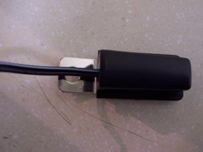
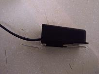
Further i am attaching the image of the hood pin switch, i donot understand how it works, hence dont know how and where to place it under the hood. Also, the manual specifies the connection for one of the wires of the hood pin switch to the 12 pin harness, however does not say whether the other one has to goto ground or positive supply.
Need help and advice
Posted By: mo12v
Date Posted: November 04, 2005 at 6:53 PM
12 PIN Harness: Where do you have # 3 & 4 connected?? What wires & Color on Vehicle? ------------- MO
Don't Learn from Others Mistakes
You Might Be the One That Knows.
Posted By: campuschill
Date Posted: November 04, 2005 at 7:27 PM
Thanks MO
I connected #3 to one of the wires of the control switch, the other wire of the switch went to ground.
I connected #4 to brake switch wire (color brown). This wire registered positive 12V when the brake was pressed.
Posted By: mo12v
Date Posted: November 04, 2005 at 7:38 PM
If you were to connect R/S ...........& Unhook TACH wire from R/S....will your Vehicle START with the Key?
-------------
MO
Don't Learn from Others Mistakes
You Might Be the One That Knows.
Posted By: campuschill
Date Posted: November 05, 2005 at 9:37 AM
I think i had a problem with ground, the van starts with the key with the same wiring as above. However no luck with the remote starter.
Do i have to connect the remaining wires, like the hood pin switch. The manual says hood pin is a negative shutdown, so leaving this un-connected should not make a difference i thought. I donot have any idea about the other wires that are left un-connected.
When i press the remote start switch, i see relay ticking noise in the module.
Please advice
Posted By: campuschill
Date Posted: November 06, 2005 at 10:23 AM
Where is the firewall connector located in a 2000 Chevy venture. I was looking for the parking lights source with brown color wire, which i was unable to locate.
I did not hook up the BYPASS module DEI555G, so i tried the remote start with the key in the ignition, no luck yet.
Please do advice on placing the hood pin trigger, based on the image above. When i press there is continuity between the wires in the hood pin switch and open when not pressed. So it looks like the switch will connect to ground when the hood is closed, is this a right setting.
Thanks for your continued response
Posted By: campuschill
Date Posted: November 07, 2005 at 8:36 PM
Can somebody help?
Posted By: campuschill
Date Posted: November 21, 2005 at 3:02 PM
I have installed a CODE ALARM CSI-400 on a 2000 Chevy Venture. I have not installed the Pass III Key bypass system yet, but would like to check if my installation works at this point. Should i just insert the ignition key in the cylinder and try the remote start or do i have to turn the key to ON position to check the remote start. Thanks.
Posted By: kgerry
Date Posted: November 21, 2005 at 3:11 PM
just slide the key in but dont turn it ... if all works good then you just have to deal with the PK 3 end of things.....
-------------
Kevin Gerry
Certified Electronics Technician
MECP First Class Installer
Owner/Installer
Classic Car Audio
since 1979
Posted By: campuschill
Date Posted: November 21, 2005 at 8:50 PM
Thanks Kevin...My current set-up does not work. The CSI-400 has a tachless mode, can i try at this mode, while removing the connection to the tach wire from the main module.
|