Adding LEDs to alarm output
Printed From: the12volt.com
Forum Name: Car Security and Convenience
Forum Discription: Car Alarms, Keyless Entries, Remote Starters, Immobilizer Bypasses, Sensors, Door Locks, Window Modules, Heated Mirrors, Heated Seats, etc.
URL: https://www.the12volt.com/installbay/forum_posts.asp?tid=68205
Printed Date: May 16, 2024 at 6:32 PM
Topic: Adding LEDs to alarm output
Posted By: vibe03
Subject: Adding LEDs to alarm output
Date Posted: December 12, 2005 at 12:24 PM
How do I add more LEDs to my alarm's output? I tried to connect a relay but was unsuccessful. I have a black widow alarm.
-------------
ART
Replies:
Posted By: auex
Date Posted: December 12, 2005 at 12:26 PM
Wire them in series.
-------------
Certified Security Specialist
Always check info with a digital multimeter.
I promise to be good.
Tell Darwin I sent you.
I've been sick lately, sorry I won't be on much.
Posted By: vibe03
Date Posted: December 12, 2005 at 12:29 PM
That would cause them to be dim. (right?) I want them to max out.
-------------
ART
Posted By: vibe03
Date Posted: December 12, 2005 at 12:34 PM
I was going for 6 LEDs. Is there any thing that I can do so that I can use all 6? Thanx for all the help. ------------- ART
Posted By: vibe03
Date Posted: December 12, 2005 at 12:45 PM
One might think that is over kill, but I am just tinkering with different things. If you make any mod to a car it is advertisment for a thief. ------------- ART
Posted By: auex
Date Posted: December 12, 2005 at 1:29 PM
Get the DEI LED sequencer. 5 led ports with up to 5 led's per port, wired in series of course.
-------------
Certified Security Specialist
Always check info with a digital multimeter.
I promise to be good.
Tell Darwin I sent you.
I've been sick lately, sorry I won't be on much.
Posted By: vibe03
Date Posted: December 12, 2005 at 4:07 PM
Thanx 4 all the help... I should be able to get this going now.
-------------
ART
Posted By: vibe03
Date Posted: December 13, 2005 at 6:38 PM
Are these 2 schemactics the same? 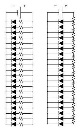
------------- ART
Posted By: vibe03
Date Posted: December 13, 2005 at 6:48 PM
Only the first LED lights up. Tested all resistors and LEDs, they are good. I would appreciate any help that can be provided. ------------- ART
Posted By: KPierson
Date Posted: December 13, 2005 at 8:33 PM
The two schematics posted are not identical. The one on the left has all the LEDs wire in parallel, with individual current limiting resistors. This should work fine, depending on how you are driving them The second schematic shows all the resistors wires in series. In a series setup like shown all the LEDs will have the same amount of current, but the voltage would be extremely low - battery voltage divided by number of LEDs - this assumes all resistors are the same value, if they are differnt values you'll create a voltage divider and your voltage output of each node will be different. ------------- Kevin Pierson
Posted By: vibe03
Date Posted: December 14, 2005 at 1:00 PM
Thanxs Kevin, for the input.
-------------
ART
Posted By: tsmithlxix
Date Posted: December 14, 2005 at 3:33 PM
If you haven't started this project yet, good, just get a simple electronic flasher (from your local auto parts joint for emergency flashers) and hook it up to your "Neg When Armed" wire. I've done the same thing with six LEDs in the headlights, fog lamps and reverse lights of my '00 DTS. They all falsh when my alarm is on. Power hasn't been an issue yet because I've left my car sitting for up to a week while on vacation and it started fine when I returned.
Posted By: dualsport
Date Posted: December 14, 2005 at 6:39 PM
If you're going to use that many LEDs (assuming you're using bare LEDs and not built-in resistor limited ones),
you could do something like this:

The resistor may not even be needed, since the voltage is divided among all 6 LEDs, so each one would get a bit over 2V.
Depends on the forward voltage rating of the LEDs you're planning on using; if it's less, then you need to add a small resistor to limit the current to keep the LEDs from blowing out.
This won't draw any extra power other than what you need for the LEDs, and I'm assuming the alarm module output is handling the flashing, which I assume you'd want. If you want it on continuously, then just find a signal output that goes to 12V when you want them on.
Posted By: vibe03
Date Posted: December 15, 2005 at 2:51 PM
Again, thanxs for all this great help. I want to use my LED OUTPUT from my alarm module and the LEDs have build-in resistors. I want to run these 6 LEDs in parallel to give them all the needed 12 volts. I would like the LEDs to flash. With that, what is the best way to do this? I am going for 2 LEDs in each front corner beam (using the winshield to enhance the lighting) and one LED in each headlight. ------------- ART
Posted By: tsmithlxix
Date Posted: December 15, 2005 at 3:02 PM
vibe03 wrote:
Again, thanxs for all this great help. I want to use my LED OUTPUT from my alarm module and the LEDs have build-in resistors. I want to run these 6 LEDs in parallel to give them all the needed 12 volts. I would like the LEDs to flash. With that, what is the best way to do this? I am going for 2 LEDs in each front corner beam (using the winshield to enhance the lighting) and one LED in each headlight.
Did you happen to read my previous post?
Posted By: dualsport
Date Posted: December 15, 2005 at 3:39 PM
Sounds like you're doing the same thing tsmithtxix did, so you can just do what he used. Just have to make sure you get the electronic type of flasher mentioned, so it's load independent, otherwise they won't flash with the small current draw of the LEDs compared to the normal incandescent lights.
If you want to have them flash in time with your existing one and keep power draw to a minimum, you could also wire it this way- 
Posted By: vibe03
Date Posted: December 15, 2005 at 7:16 PM
tsmithtxix, sorry about that just didn't see your post. So, the only thing the electronic flasher will do is make the LEDs brighter. If so, is there much of a difference? Dualsport and tsmithtxix thanks for the input and dealing with my many questions. I am just trying to get this electronic stuff down. ------------- ART
Posted By: tsmithlxix
Date Posted: December 15, 2005 at 7:34 PM
vibe03 wrote:
tsmithtxix, sorry about that just didn't see your post. So, the only thing the electronic flasher will do is make the LEDs brighter. If so, is there much of a difference? Dualsport and tsmithtxix thanks for the input and dealing with my many questions. I am just trying to get this electronic stuff down.
No, it doesn't make the LEDs brighter. Your LEDs will only be as bright as they're supposed to be with a 12VDC input. The only thing the flasher does is make your LEDs flash at whatever rate the flasher flashes. If I remember correctly (sorry, it's been a couple of years since I installed it) there are 3 posts on the flasher. I have a constant 12VDC going to one post of the flasher, the LEDs' positive lead to the second post, and I have my "NEG WHEN ARMED" wire from my alarm going to the 3rd flasher post. This way, when I arm my alarm, the flasher is activated and my LEDs begin to flash. No they do not flash at the same rate as the alarm LED; they're totally independent from that. But, ya know, who's gonna notice that, besides me... and maybe you... and whomever else is reading this thread. :o) I also remember that I wrapped some foam around the flasher when I was done too, because the clicking of the flasher is pretty loud and you could actually hear it outside the car. I thought that was a little ghetto, so I added the foam as a little sound insulation. I know, that's a little ghetto too but only I know it's there... and now you... and whomever else is reading this thread. :o)
Posted By: dualsport
Date Posted: December 15, 2005 at 7:58 PM
Yeah, the electronic flasher doesn't make the LEDs brighter; think of it as a switch; when you apply power across it, the switch will just keep opening and closing, giving you the flashing feature.
Advantage of using it is that it's simple to hook up, and maybe more rugged than using the transistor, since you don't have to worry about static damage when handling it while unconnected.
It'll use more power, since it uses a mechanical relay to do the switching, needing power for the relay coil. The transistor wouldn't use any extra power, so if you want to minimize the drain on the battery, that would help.
The flash rate and on/off time of the LEDs will be probably different from using the alarm's LED output as the control, you'd have to see which one you like better.
A benefit of using the alarm LED output might be to allow you to see the LEDs from a distance for a status indication, which could come in handy sometimes.
I just like using these transistors for everything because I bought a bagful for 10c a piece, and they're pretty useful for different purposes. Just takes more care when wiring them up, because they're easily zapped with static until connected to the circuit. The flasher makes for a more foolproof installation, since it wouldn't be prone to that.
So you have two possibilities to play with- 
Posted By: vibe03
Date Posted: December 16, 2005 at 3:56 PM
Great... Choices are good. Now the hardest part, flasher or transistor. 
------------- ART
Posted By: vibe03
Date Posted: December 17, 2005 at 7:22 PM
Dualsport what program did you use to draw that schematic?
-------------
ART
Posted By: dualsport
Date Posted: December 17, 2005 at 9:30 PM
That's using Orcad Capture- makes things really easy to draw up.
Posted By: l0gik2
Date Posted: January 08, 2006 at 4:25 PM
I have a python 1500 esp I need to add leds to it. The manual doesn't specify the voltage output for the status led. I put it on my multimeter and it registered about 2v. I'm assuming this is correct unless someone says it should be 12v. The leds i'm putting on are 3.5v. I plan on using the red 2v led and 2 of my blue 3.5 v leds in a series with no resistors. What do you think? I don't care about burning up leds I just don't want to burn up part of the alarm. The leds are 6k mcd so even at 2 volts it will be really bright. I was going to hook it up n test it out, but thought I would ask here first.
Posted By: dualsport
Date Posted: January 08, 2006 at 4:40 PM
If the alarm's only putting out 2V, it's probably not going to light up when you have those three LEDs in series, not enough voltage to drive them that way.
Might have a chance if you put them in parallel, though the blue LEDs may still be pretty dim, if they have a forward voltage of 3.5V.
Posted By: l0gik2
Date Posted: January 09, 2006 at 12:37 AM
I don't know if I completely trust my multimeter but it goes from 0 to 2 v pulsing with the led. Does that seem odd or normal? I already tried to connect the led in parallel with the stock 2v led and it didn't work at all. Do u think I just need to get some 12v leds and do one of the wiring diagrams listed previously in this post?
Posted By: dualsport
Date Posted: January 09, 2006 at 1:08 AM
Your DMM probably doesn't update fast enough to give a good reading when it's pulsing rather than on steady, but it sounds like the alarm has the limiting resistor built into the unit. If that's the case, you'd probably need to make up your own circuit to drive more LEDs.
If you have a diode and a cap, you can try using that with your DMM to get a better idea of the open circuit peak voltage being put out from the alarm's LED drive. If it's at least 3V, you can use it to control a BS170 transistor to drive the extra LEDs.
Posted By: l0gik2
Date Posted: January 09, 2006 at 11:45 PM
I don't have a diode or cap on hand is it safe to assume it is probably around 3v? I am unable to find any other information about the power output. I would assume all DEI alarms are prettty similar right? I am going to wire 3 leds in a series and connect them to see if it will drive the 3 leds. Voltage shouldn't be an issue if its at or near the leds forward voltage right? I think it would be more about amps drawn or rather mA. Each led pulling about 20mA.
Posted By: dualsport
Date Posted: January 10, 2006 at 10:25 AM
Won't hurt to give it a try, but I don't think it'll light up.
You have to have enough voltage to push the current through the diodes, and if you have three in series, you need to add up all the forward voltages of the LEDs for the required drive voltage.
Posted By: l0gik2
Date Posted: January 10, 2006 at 2:06 PM
I want to do 4 or 5. 1 on each door, 1 in each headlight and one in the console. But I don't care as much about the one in the console. To do that I would have to use a relay or something right to get more power to them? Can someone draw me up a diagram for wiring it? I just don't know where to get a 3.5 v power supply from or I could just use 12v and use resistors to all of the leds. BTW thx for all the help, I am gonig to hook up 3 leds later today and see how well it works if at all. bobk, where did you find that information? I could use resources like that.
Posted By: KPierson
Date Posted: January 10, 2006 at 2:43 PM
Use a transistor, a 2n3906 should work great. Wire the switching (-) LED output of the alarm though a 220 ohm resistor to the base of the transistor. Wire the emitter to 12vdc and then connect the collector through a 470 ohm resistor to the + side of your LEDs. You can hook them all in parallel, and then hook all their grounds to ground. ------------- Kevin Pierson
Posted By: dualsport
Date Posted: January 10, 2006 at 5:58 PM
Well, decided to look further at how this is set up instead of trying to guess-
From the manual of the Viper 300 ESP, which I'll assume may use the same LED drive setup, it says:
The super bright LED operates at 2V DC. Make sure the LED wires are not shorted to ground as the LED will be damaged. Multiple LED's can be used, but they must be wired in series.
Sounds like the output uses a current driver, so the series connection will work, since the alarm should adjust the output voltage differential to push the specified current, as long as you don't have too many hooked up. If you use the higher voltage LEDs you'll hit the voltage limit sooner.
It might be kind of a pain to hook all your LED's in series with a ring pattern, because you can't use a common ground, which is the advantage of doing it like Kevin outlined, which lets you wire in together with single wires radiating out from the controller.
The hookup to the transistor may have to be tweaked though, because it doesn't sound like the alarm module output switches to ground when it lights up the LED, but instead drops it to 10V, when a single LED is connected.
That's something you'll have to verify.
When you measured the output of the alarm and saw the 2V, were you measuring between the two wires going to the LED? If you measure from the wires to ground, I think you may see closer to 12V when it's off.
Posted By: KPierson
Date Posted: January 10, 2006 at 10:15 PM
I built an LED flasher quite a few years ago that ran off of the LED port of a DEI alarm. If my memory serves me correctly the + side had a constant 5vdc on it, and the (-) side switched between open and ground. I remember this because I built the flasher originally to work off of a switched (+) and had a nice surprise waiting for me when I tried to hook it up in the guys truck that I built it for. Its interesting that they tell you not to ground the wires, as to not damage the LED. That sounds like the (+) side of the port is tied directly to a power supply.(be it 2,3, or 1000volts) and the ground has a resistor in line with it. Thats the only way I can think of that would risk damaging the LED if you ground out the ground wire. Anyways, let us know what you find. I have an old DEI alarm sitting at my parents house, next time I'm over there I might pull it out and hook it up. ------------- Kevin Pierson
Posted By: dualsport
Date Posted: January 10, 2006 at 10:35 PM
The +5V source makes sense and would match up with bobk's info that only a maximum of 3 LEDs could be connected in series-
Any more and there wouldn't be enough voltage per LED.
The control side must be configured for a constant current, to maintain the same brightness regardless of the number of LED's connected (up to the limit anyway).
Since he's planning on using LEDs with a higher Vf, it'd probably only be good for maybe one blue along with the original red LED, before dropping in brightness too much.
I'd guess the string of LEDs could be powered with 12V instead of the 5V from the alarm, with the alarm's control side output used to sink the 20mA current from the other end, but that might be risky without first doing some verification.
Even so, the PNP transistor still sounds like the best way to go about it-
|