decifer diagram?
Printed From: the12volt.com
Forum Name: Relays
Forum Discription: Relay Diagrams, SPDT Relays, SPST Relays, DPDT Relays, Latching Relays, etc.
URL: https://www.the12volt.com/installbay/forum_posts.asp?tid=109147
Printed Date: May 22, 2024 at 9:30 PM
Topic: decifer diagram?
Posted By: blkrhyno
Subject: decifer diagram?
Date Posted: November 22, 2008 at 3:44 PM
Can someone please help me decifer the bottom half of the diagram below. I have cd40106 chips with 14 pins but I can't figure out from the diagram below which pins to connect to and where to place the diodes, caps & resistors. What is a BS170 and how do i connect it. Any healp would be greatly appreciated. Thanks. https://images32.fotosik.pl/341/80aa5e8b95c9d145.png ------------- Protect what's yours.
Replies:
Posted By: i am an idiot
Date Posted: November 22, 2008 at 5:04 PM
Posted By: blkrhyno
Date Posted: November 22, 2008 at 6:06 PM
Thank you, so the 1,2, & 3 on the bs170 are the pins right?
-------------
Protect what's yours.
Posted By: i am an idiot
Date Posted: November 22, 2008 at 6:31 PM
Drain = pin 1 Gate = pin 2 Source = pin 3. The PDF I posted uses D G and S.
Posted By: blkrhyno
Date Posted: November 22, 2008 at 7:32 PM
ok thank you i understan now, I'll have to order some of those, thaks again for your help
-------------
Protect what's yours.
Posted By: hotwaterwizard
Date Posted: November 25, 2008 at 10:11 PM
OK what are you trying to do with this Circuit? The IC and Transistors are Static sensitive you must wear a wrist strap to ground while touching these components also a Grounded Soldering iron. The components will fry with static electricity. One little spark is all it would take. Handling MOSFETs https://www.irf.com/technical-info/appnotes/an-955.pdf BS170 Datasheet https://www.onsemi.com/pub_link/Collateral/BS170-D.PDF CD40106 Datasheet https://www.fairchildsemi.com/ds/CD/CD40106BC.pdf The IC pins start with #1 at the Dot. 
------------- John DeRosa (Hotwaterwizard)
Stockton California
When in doubt, try it out !
Posted By: dualsport
Date Posted: November 26, 2008 at 8:37 PM
That was from an old post for controlling a folding power mirror. Don't know it anything came out of it though.
Posted By: blkrhyno
Date Posted: November 26, 2008 at 10:42 PM
That was from an old post for controlling a folding power mirror. Don't know it anything came out of it though. Yes that is what I was trying to do but I wanted to do it when I turn the car off and on. Then I found your diagram and decided to try it that way because I did get any responses from my post about the power folding mirrors. Some of the things I didn't understand until "i am a idiot" cleared it up for me. Are you not sure if the diagram works? ------------- Protect what's yours.
Posted By: dualsport
Date Posted: November 26, 2008 at 10:58 PM
It just didn't look like he tried putting it together, guess it might have been too much to attempt for someone unfamiliar with electronic bits.
It definitely needs more care than working with relays because of what Hotwaterwiz mentioned. Can't kill a relay touching them after shuffling through your living room petting your furry cat, but FETs and CMOS stuff are easily zapped when handling them unprotected. Just get your strap on and you should be fine- 
Posted By: dualsport
Date Posted: November 26, 2008 at 11:18 PM
By the way, have to say I was curious what a decifer diagram was- sounded like some roadmap for the black arts or something.
Hopefully it got deciphered okay.
Posted By: blkrhyno
Date Posted: November 26, 2008 at 11:29 PM
LOL, thanks for your help.
-------------
Protect what's yours.
Posted By: i am an idiot
Date Posted: November 27, 2008 at 12:51 AM
Have any of you actually damaged an FET from static electricity?
Posted By: hotwaterwizard
Date Posted: November 28, 2008 at 8:59 AM
Yes I have I was installing them in a car Amplifier and it didn't work. I found out from the school of hard knocks that you must wear a grounding strap and absoloutly no wool or poly. I tried to return them to the electronics store I bought them at and they ended up selling me this rinkey dink wrist band with a wire and clip. I ended up making my own by wraping some wire around my metal band flexable wrist watch and running a wire to a water pipe. Most houses these days have plastic pipes so I had to run a 4 ft rebarb into the ground and tie the other end of the wire to that. Another easy way is to wrap a strand of wire around all of the pins before you solder it into the board and unwrap the wire after it is soldered in. I also use a grounded soldering iron. ------------- John DeRosa (Hotwaterwizard)
Stockton California
When in doubt, try it out !
Posted By: i am an idiot
Date Posted: November 28, 2008 at 9:21 AM
I guess that I am a permanent ground. I have even tried to zap them with no luck, walking across the carpet charging my body and then touch the device. Have tried on several occasions. I know several people who do this for a living, nobody uses any kind of protection.
Posted By: ckeeler
Date Posted: November 28, 2008 at 9:39 AM
i am an idiot wrote:
I guess that I am a permanent ground. I have even tried to zap them with no luck, walking across the carpet charging my body and then touch the device. Have tried on several occasions. I know several people who do this for a living, nobody uses any kind of protection.
same here, ive never zapped anything. ive even tried. i also know several people including my brother who do this for a living and have never zapped anything and never use a grounging strap. i asked my brother about using one and he just laughed at me. Weird. hotwaterwizard must just has that "magic" touch that wizards have.
Posted By: hotwaterwizard
Date Posted: November 28, 2008 at 10:16 AM
Some devices are more sensitive than others. A regular FET is not sensitive. MOSFET is. IRFZ40 for example is static sensitive that is why they send them in a special shielded bag. ------------- John DeRosa (Hotwaterwizard)
Stockton California
When in doubt, try it out !
Posted By: dualsport
Date Posted: November 28, 2008 at 10:33 AM
You guys aren't suggesting ESD damage is a myth?
There's a great deal of variation in ESD susceptibility. Depends on the type of components you're dealing with, humidity in the air, clothing, shoes, etc.
If you work with regular transistors all the time you're more likely to get away without protection, but components with high impedance inputs are going to be much more liable to get damaged. And damage can be latent, where it's not an immediate outright failure but degraded operation. Not always as obvious a result as with condoms maybe but it's just a matter of reducing the odds of a mishap..
Not having personally seen the earth isn't really flat, doesn't mean it is-
Posted By: ckeeler
Date Posted: November 28, 2008 at 10:45 AM
haha, calm down dualsport. of course we are not suggesting that. that would be just plain ignorant now wouldnt it? what we are saying, is that we have never done it before. even on purpose ive never done it. ive tried. not saying it doesnt happen......saying ive never been able to do it (knock on wood).
Posted By: dualsport
Date Posted: November 28, 2008 at 11:26 AM
Posted By: hotwaterwizard
Date Posted: November 28, 2008 at 11:28 AM
 ------------- John DeRosa (Hotwaterwizard)
Stockton California
When in doubt, try it out !
Posted By: blkrhyno
Date Posted: November 29, 2008 at 9:56 PM
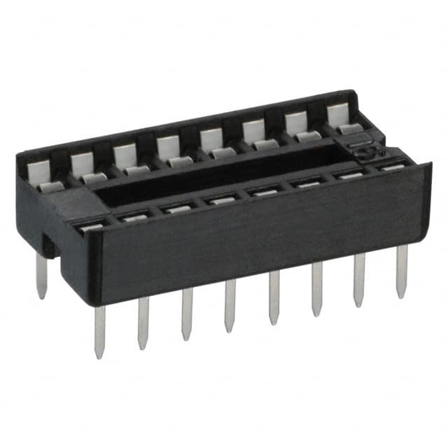
You guys are funny, i know this must be a stupid question but do i need a board to solder these chips too? I can't just run a wire from them like I would a relay right? Sorry iif my questions seem stupid I'm just use to doing alarms and stereos.
-------------
Protect what's yours.
Posted By: hotwaterwizard
Date Posted: November 30, 2008 at 8:04 AM
I would suggest a Perf board or an IC circuit board from Radio Shack https://www.radioshack.com/product/index.jsp?productid=2103799 
------------- John DeRosa (Hotwaterwizard)
Stockton California
When in doubt, try it out !
Posted By: i am an idiot
Date Posted: November 30, 2008 at 8:30 AM
I suggest the same type of board. A lot of times their boards sit on the shelf for a while, you may want to use some 400 grit sandpaper to remove the oxidation from the solder pads. It will make it much easier to solder onto the pads.
Posted By: dualsport
Date Posted: November 30, 2008 at 8:42 AM
Along with the suggestions for the board, you can also get IC sockets that will let you plug in the chip after you're all done wiring.
You can solder in the socket without worrying about damaging the chip.
If you ever find a need to replace the chip, you'll be happy you can just pull it out and simply plug in the new one-
Something like this is 18 cents from digikey-
Posted By: hotwaterwizard
Date Posted: November 30, 2008 at 11:34 AM
https://www.radioshack.com/product/index.jsp?productid=2062607 
Radio Shack no shipping no waiting. ------------- John DeRosa (Hotwaterwizard)
Stockton California
When in doubt, try it out !
Posted By: blkrhyno
Date Posted: November 30, 2008 at 4:30 PM
Thanks, you guys are extremely helpful. I have another stupid question, do I wire the diodes, resistors & caps on the wire or on the board? Is it at all possible for one of you guys to draw a diagram showing how it should be wired on the board? ------------- Protect what's yours.
Posted By: dualsport
Date Posted: December 01, 2008 at 11:04 PM
You should be able to put all the components on the board. You know how to use a soldering iron, I assume- If you print out the schematic you can just use a highlighter to mark off the connections you've made, and just go until you have everything connected. That'll help you keep track of what else you have to connect together as you go.
Use sockets for the IC and transistors, the other stuff you should be able to solder on directly, as they're more rugged.
If you anticipate needing to modify the timing, you can use sockets for the resistor and cap to be able to easily change them by plugging in new values.
Posted By: blkrhyno
Date Posted: December 02, 2008 at 5:27 PM
Yes I know how to use a soldering iron, thank you for all your help, I'll let you know how it works out.
-------------
Protect what's yours.
Posted By: blkrhyno
Date Posted: December 02, 2008 at 7:01 PM
Sorry one more question, do I run wires from the board to the relays? In other words, how do i connect the curcuit board to the relays?
-------------
Protect what's yours.
Posted By: dualsport
Date Posted: December 02, 2008 at 7:39 PM
I assume you're not going to use any board mount type relays, but the standard automotive types with the blade connectors, so you'll be connecting wires to the board-
Get one of the commonly available relay socket harnesses, and you can connect the wires from the harness to the board and plug the relays into the harness sockets.
Posted By: blkrhyno
Date Posted: December 02, 2008 at 9:53 PM
Thanks dualsport, much appreciated.
-------------
Protect what's yours.
Posted By: hotwaterwizard
Date Posted: December 03, 2008 at 1:39 AM
Email me for a possible layout hotwaterwizard@aol.com ------------- John DeRosa (Hotwaterwizard)
Stockton California
When in doubt, try it out !
Posted By: blkrhyno
Date Posted: December 04, 2008 at 7:45 PM
hotwaterwizard wrote:
Email me for a possible layout hotwaterwizard@aol.com
You have email ------------- Protect what's yours.
Posted By: blkrhyno
Date Posted: December 13, 2008 at 3:59 PM
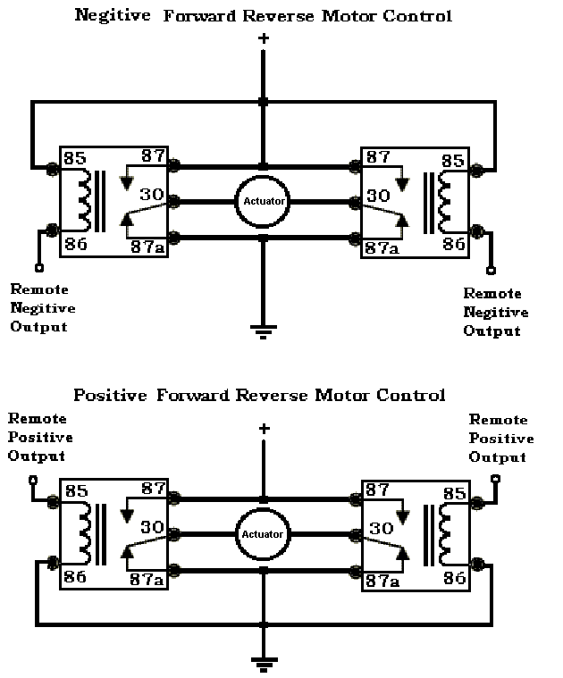
Ok guys, I started to build the circuit but after taking a closer look at the relays I realize that one wire for the power mirrors will be neg(-) and the other will be pos(+). The problem is, there is only one wire that controls the mirrors, it is sends a pos(+) signal when they open and a neg(-) signal when they close on the same wire. Can anyone help me?
-------------
Protect what's yours.
Posted By: dualsport
Date Posted: December 13, 2008 at 6:19 PM
The purpose of the circuit was to provide a reversing polarity signal to power the mirrors, if you're going to use a control signal an existing driver circuit, then you don't need this somewhat involved relay setup.
You'll have to make sure your control circuit input will tolerate your externally grounding or applying 12V to it when the switches are in their normal standby position. If it's simply a double throw switch you could get away with it, but if there are electronics involved, you have to make sure you know what's in there first to avoid possible damage.
Try to describe exactly what you have to control, and what controls you'll be driving it with.
Posted By: blkrhyno
Date Posted: December 13, 2008 at 8:41 PM
It's my personal car, an 04 Audi A6. It as a switch that controls the mirrors folding in & out which also controls adjustment of the glass itself. I originally wanted to have them fold in & out with the ignition. Here are the wires: yellow/blk = (-) always WHITE/ blue = (-) only w/ mirrors open PURPLE / blk = (-) always lt green = (-) always brown = (-) always blk/red = (+) 12v always lt GREEN/ YELLOW = (-) with switch in close position, (+) 12v in open position grey/blue = (-) always RED / yellow = (-) always ------------- Protect what's yours.
Posted By: i am an idiot
Date Posted: December 13, 2008 at 9:20 PM
Is there a positive voltage on the WHITE/ Blue wire when the mirror is closed? The switch to open or close, is it a spring loaded switch with a center position?
Posted By: blkrhyno
Date Posted: December 13, 2008 at 9:37 PM
They isn't any voltage on the WHITE/ blue wire with the mirror closed and yes it is a spring loaded swithch with a center position.
-------------
Protect what's yours.
Posted By: dualsport
Date Posted: December 13, 2008 at 9:48 PM
Not sure what wires you have listed there, are those wires in the connector for the power mirror itself? Or is that from the switch? Without a diagram of what they're connected to, it's difficult to figure out, not having wire schematics for the specific car.
Is it the lt GREEN/ YELLOW or the WHITE/ blue wire you were going to control the mirror folding with?
Have you tried to control the mirrors by applying a signal directly?
You'll have to find out if it just needs a ground or +12V to be applied to move the mirrors, or if it's locked at some state in standby by the existing switch.
Posted By: dualsport
Date Posted: December 13, 2008 at 9:53 PM
when you say with the mirror closed, are you referring to the position of the mirror, (folded in or out)? Is it something like a microswitch to detect if the mirror is fully folded in, as a feedback for the control?
I never had any folding mirrors to play with, so I don't know the setup. Is it a momentary push on a button, and then the mirrors go out to the position and stop automatically, or do you have to hold it and manually stop it when it hits the stop?
Posted By: blkrhyno
Date Posted: December 13, 2008 at 10:38 PM
The wires listed is the wires coming from the mirror switch. I used my power probe to send +12v to the lt GREEN/ YELLOW wire and the mirrors fold out(open), when I take the +12v off the lt GREEN/ YELLOW wire the mirrors fold in(close). The switch has three positions like any other mirror switch but also has a fourth position to fold them in, when I turn the switch to either the driver side, passenger side or center position they fold out. When I probe the lt GREEN/ YELLOW wire when folding the mirrors in it shows (-), when I probe the same wire folding the mirrors out it shows +12v. The only other wire that shows any change is the WHITE/ blue wire that shows (-) only when I fold the mirrors out, all the other wires stay the same. Once I twist the switch for the mirrors to fold out they stop automatically and i don't have to hold the switch the that position.
-------------
Protect what's yours.
Posted By: dualsport
Date Posted: December 13, 2008 at 11:41 PM
I assume you were using your power probe on it while it was all connected together, and the switch was in the folded in (closed) position.
It sounds like the mirrors will fold in if you were to open up the connection from the LG/YL wire, which would remove the 12V from the control circuit. Is it sitting at 12V whenever you have the mirror switch in the operate positions?
Maybe you could do something simple like just wire a relay that's energized by the ignition, and use the normally open contact to provide the connection for the LG/YL wire. When the ignition is off, the relay opens, and the mirrors would fold in.
If this works, you might want to add another switch in the event you want the mirrors to be out even with the ignition off (maybe use it when you just park temporarily, sitting in the car, so it doesn't cycle the mirrors unnecessarily every time you switch the ignition on and off).
Posted By: blkrhyno
Date Posted: December 14, 2008 at 7:52 AM
Yes the switch is sitting at 12v in the operating positions. I try that and see what happens
-------------
Protect what's yours.
Posted By: dualsport
Date Posted: December 14, 2008 at 8:06 AM
Also see if the WHITE/ blue wire shows the same change when it folds, in case it's used to signal the end of travel. You want to be sure this doesn't keep applying power even after it's done.
Posted By: i am an idiot
Date Posted: December 14, 2008 at 8:16 AM
In case there is no limit switch, unplug one of the mirrors and replace the fuse in the car with a 3 or a 5 amp fuse. Also monitor the connected mirror and if you hear the motor continue to run, unplug it.
Posted By: blkrhyno
Date Posted: December 14, 2008 at 5:59 PM
Thanks once again guys for sharing your knowledge, much appreciated. Do you guys think that I'm gonna need a few relays wired the same way to move the mirrors?
-------------
Protect what's yours.
Posted By: hotwaterwizard
Date Posted: December 15, 2008 at 12:52 AM
Just 2 relays nothing else 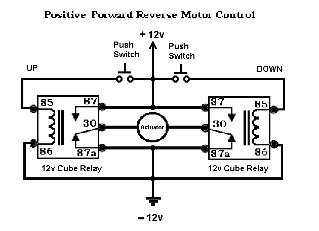 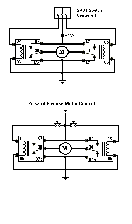 ------------- John DeRosa (Hotwaterwizard)
Stockton California
When in doubt, try it out !
Posted By: blkrhyno
Date Posted: December 16, 2008 at 10:32 PM
Thanks wizard
-------------
Protect what's yours.
|

