Latching Relay to Use a Momentary Button
Printed From: the12volt.com
Forum Name: Relays
Forum Discription: Relay Diagrams, SPDT Relays, SPST Relays, DPDT Relays, Latching Relays, etc.
URL: https://www.the12volt.com/installbay/forum_posts.asp?tid=111048
Printed Date: April 30, 2024 at 11:41 AM
Topic: Latching Relay to Use a Momentary Button
Posted By: lostissues
Subject: Latching Relay to Use a Momentary Button
Date Posted: January 27, 2009 at 2:13 PM
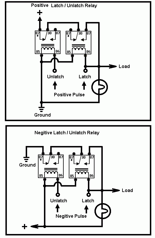
Ok I know that you can make a latching relay with the diagram provided on this site. I have done it and it works great for my application. the only problem is that it takes a little while to set up, it doesn't look the nicest, and it is rather large. I was even using 4 mini relays but it was still a little to big because I plan on using a few of them. What I'm hoping to find is a 12 volt latching relay, I will use a momentary push button to turn on and off the latching relay. the latching relay will provide a trigger to activate a regular 30/40 amp relay. if anyone knows where I can get a latching relay, maybe something that I could put on a PCB board that would be awesome. Jonathan
Replies:
Posted By: ckeeler
Date Posted: January 27, 2009 at 2:52 PM
check out this thread. haha, i had the same question too. finally one of the guys found something. it wasnt what i wanted originally, but its gonna work just fine. https://www.the12volt.com/installbay/forum_posts.asp?tid=110908&KW=ckeeler&tpn=1
Posted By: lostissues
Date Posted: January 27, 2009 at 3:47 PM
https://www.the12volt.com/relays/page5.asp#lsp This is the diagram that I was talking about. I was able to make it with mini relays and it worked great its just a little big. I cannot believe that there is no readily available product that can do this. the 0047 looks like it will do what I'm looking to do. were you ever able to find a place to purchase them? how much do they run? https://search.digikey.com/scripts/DkSearch/dksus.dll?Detail&name=255-2193-ND are you saying that this relay will not work? because you could not apply a negative pulse to it to turn it on and another negative pulse to turn it off. also 5 bucks is a little pricey for me. Thanks, Jonathan
Posted By: ckeeler
Date Posted: January 27, 2009 at 3:56 PM
if you read the data sheet for that relay on digikey you will see it doesnt work like you want it to. in order to latch and unlatch the load contacts, the polarity on the coil contacts has to be flip-flopped back and forth. the 0047 is more than $5.
Posted By: lostissues
Date Posted: January 27, 2009 at 4:17 PM
I kind of figured that it would be hard to find a smaller, cheap solution. Either I will have to make my own and have it take up a lot of room or pay a lot of money. if only I could adapt something like this to work off of negative triggers instead of a remote it would be perfect. https://www.electrokits.com/electronics/relays-remotes-switches-timers/37.htm well thanks for your help. Jonathan
Posted By: hotwaterwizard
Date Posted: January 28, 2009 at 1:01 AM
611t_timed_latch_relay.pdf------------- John DeRosa (Hotwaterwizard)
Stockton California
When in doubt, try it out !
Posted By: hotwaterwizard
Date Posted: January 28, 2009 at 1:11 AM

------------- John DeRosa (Hotwaterwizard)
Stockton California
When in doubt, try it out !
Posted By: ckeeler
Date Posted: January 28, 2009 at 9:50 AM
hotwaterwizard wrote:
611t_timed_latch_relay.pdf
Thank You Wizard! i never knew about this product. looks perfect! i will try a few.
Posted By: KPierson
Date Posted: January 28, 2009 at 11:06 AM
There is a component called a D Flip Flop that can be set up in toggle mode that will toggle it's output between on and off each time the button is pushed. They are very cheap and work well (as long as you debounce the input). Schematics (with debounced input) should be easy to find on the net. ------------- Kevin Pierson
Posted By: lostissues
Date Posted: January 28, 2009 at 7:31 PM
cool, as for the dei 611t. it looks like it will do exactly what I want it to do, but again the size and price (low of about 13 bucks) it will not fit what I'm looking for. as for the latch/ unlatch it will not work for my application, that would require an on and an off button so it would use 2 momentary buttons instead of the one that I'm looking to control it. the D flip flop has me confused as heck. but with some quick searching it looks like it would take quite a few resistors and transistors to get it working again going back to the size thing. I found a page that shows how to make it with a transistor, a few resistors a cap and a relay https://ourworld.compuserve.com/homepages/Bill_Bowden/page9.htm#toggle3.gif that site also shows a few different ways to make something similar. this is the main page and the ones that look like they will work are on the right side of the page under "Miscellaneous" and "Circuits Controlling Relays" some use 555 chips and others use MOSFET0s. now I just have to figure out how to use and what theses components are. the schematics look pretty simple but I do now know what a few of the components are on some. once I figure out what they are there is also the question of how much do they cost. as of right now I can make a messy looking but functional "Latched On/Off Output Using a Single Momentary Pulse" like shown on this site. here is mine The top looks nice, I even added another plug part for power, ground and output. the plug on there is for the button with also has an led in it. 
But this is the bottom, it is a little neater after I added the plug for power, ground, and the output but it is still messy: 
Since I plan on using 4 or more buttons, making and placing 4 of these plus the 30/40 amp relays these will trigger that would take a lot of time and take up a lot of room. that's why I was hoping to find a single cheep latching on off relay. but it seams I will have to do some fabricating and circuit building to get what I'm looking for. Thanks for the help. Jonathan
Posted By: KPierson
Date Posted: January 28, 2009 at 8:55 PM
If size and cost are the primary concern I would recomend going with a microcontroller. The size would be extremely small and the cost would be fairly low. The only issue is developing the code and programming the chip. The cool thing about a microcontroller is you can do all the debounce stuff with software so you can eliminate quite a bit of circuitry for each button. I could build a 3 pushbutton in / 3 relay out circuit for under $10 worth of parts (not counting the pushbuttons or the actual relays). Like I said, low cost! ------------- Kevin Pierson
Posted By: lostissues
Date Posted: January 28, 2009 at 10:41 PM
The mirco controller sounds like a cool idea but I don't know the first thing about them. I would be completely lost I have never worked with them and I have no idea what kind of code I would have to learn to program them, I doubt that any code I know will be usefully. I already have the push buttons and I have a pretty good source for the relays that you see in the pic.
Posted By: KPierson
Date Posted: January 29, 2009 at 5:16 AM
If you would like to go that route I would be more then willing to help.
-------------
Kevin Pierson
Posted By: hotwaterwizard
Date Posted: February 01, 2009 at 1:18 PM
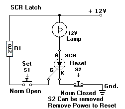
You could use an SCR but you have to remove power to unlatch it. 
------------- John DeRosa (Hotwaterwizard)
Stockton California
When in doubt, try it out !
Posted By: rfhelp
Date Posted: March 23, 2009 at 4:15 AM
hotwaterwizard wrote:
You could use an SCR but you have to remove power to unlatch it. 
Don't know what this is but I think it is what I am looking for. I want a 12v output controled by a mom pulse but will stay active until I turn off secondary switch. So, trip rocker switch to power rfid module, activate rfid with fob tripping a latching relay of some sort enabling me to put the fob back into my pocket while maintaining circuit output of 12v. Then when I turn off the rocker switch it resets the system so no power will flow until the fob is reconized again. will this do it? Can someone explain how it works to a layman?
Posted By: dualsport
Date Posted: March 25, 2009 at 12:04 AM
It should work for what you're doing.
S6025L SCR datasheet
When a small trigger input is applied to the gate, the SCR will start to conduct, and remain latched on until the current drops below a small holding current, about 50mA. If you momentarily remove power with your toggle, it'll turn off until the gate trigger is applied again.
Posted By: jdub765
Date Posted: April 03, 2009 at 8:29 PM
I'm not sure if you need this info anymore, but I posted a possible solution in this thread that you linked off of this one.
https://www.the12volt.com/installbay/forum_posts.asp~TID~110908~get~last
I'm going to try to use a 4027 chip.
|


