I need help configuring and setting up a relay(s) that will do the following.
My 12 volt motor is normally off. When I push a 2 button remote control I want the first button to make the motor run clockwise. When I push the second button of the remote I want the motor to run counter-clockwise. How would I wire this and what type and how many relays would I need to accomplish this polarity switching?
Thanks in advance.
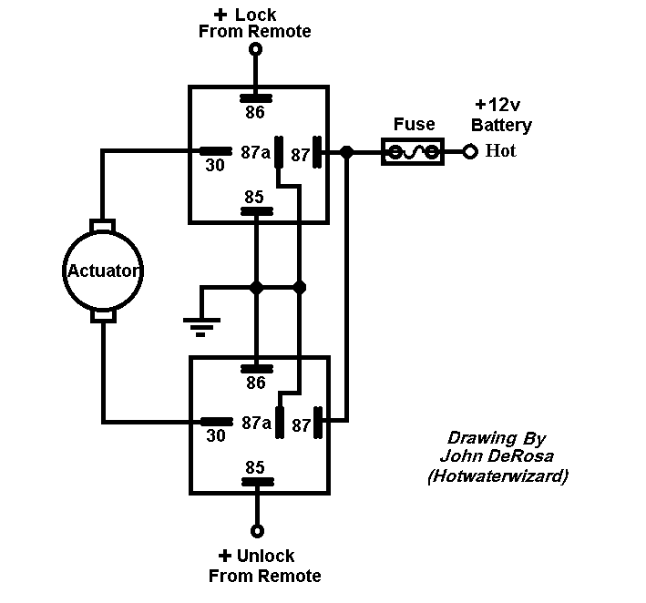
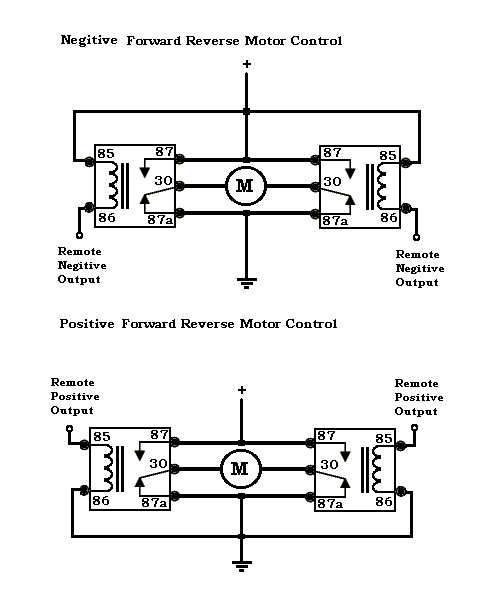
Scroll down to the diagram for Actuators/Reverse The 2 wires that are labeled to Actuators should now read to Motor. All other connections are labeled properly for your application.
-------------
John DeRosa (Hotwaterwizard)
Stockton California
When in doubt, try it out !
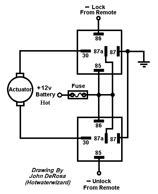
Most alarm outputs are negative. The above diagram is designed to work with a positive out. Following is the diagram I referenced earlier. It uses a negative output to trigger it.
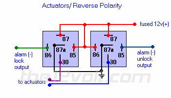
Whoopdie Do just switch around a couple of wires.
-------------
John DeRosa (Hotwaterwizard)
Stockton California
When in doubt, try it out !
I am pretty sure that if he noticed that there was a problem with the setup, he probably would not have been here asking for help.
Thanks for the info guys, it was very helpful.
Just as an FYI on what I'm trying to do, this setup is for my boat lift. I have a 12 Volt motor that I attached to the lift wheel and to move the lift up and down the motor just has the polarity reversed. I want to be able to install a low volated remote control switch that I can operate from inside my boat while the 12 volt motor draws around 25 to 30 amps, thus the need for a relay.
Depending on whether your remote device puts out a negative or a positive voltage, you have a diagram for each. Good Luck and let us know how it works out.
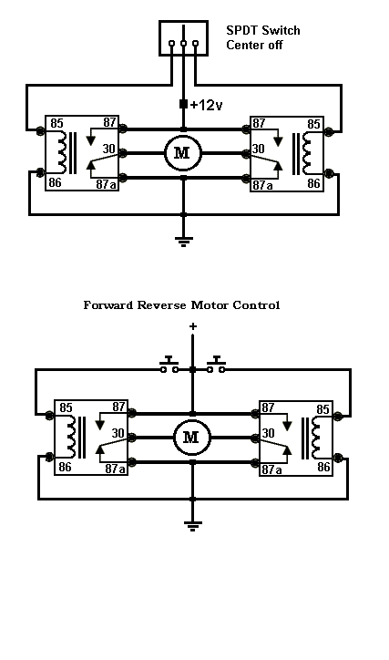
If you examine the circuits all 3 are basicly the same circuit with different hot and grounds. If you want the switch version here it is.
-------------
John DeRosa (Hotwaterwizard)
Stockton California
When in doubt, try it out !


