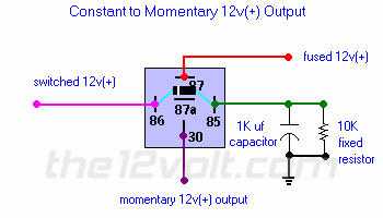
admin i need a diagram
Printed From: the12volt.com
Forum Name: Relays
Forum Discription: Relay Diagrams, SPDT Relays, SPST Relays, DPDT Relays, Latching Relays, etc.
URL: https://www.the12volt.com/installbay/forum_posts.asp?tid=114689
Printed Date: Mayá15, 2024 at 9:20 PM
Topic: admin i need a diagram
Posted By: i am an idiot
Subject: admin i need a diagram
Date Posted: Juneá25, 2009 at 7:25 PM
I am pretty sure it was here where I saw it. It made a brief pulse when 12 volts was applied and retained. When that voltage was released, it made another brief pulse. So it basically took a steady 12 volts and converted it to a pulse and then another pulse when the voltage was released. I have searched the site several times, maybe it was somewhere else. Thanks in advance.
-------------
Let's Go Brandon Brown. Congratulations on your first Xfinity Series Win. LGBFJB
Replies:
Posted By: the12volt
Date Posted: Juneá25, 2009 at 8:28 PM
I vaguely recall creating something like that. I'll try to search for it when I get in. -------------  the12volt Ľ Support the12volt.com the12volt Ľ Support the12volt.com
Posted By: i am an idiot
Date Posted: Juneá25, 2009 at 8:40 PM
Don't hurt yourself, Ihave it figured out, but it is going to take 3 relays. But if you can find it, I am sure he would be better off with a single relay. Thanks
-------------
Let's Go Brandon Brown. Congratulations on your first Xfinity Series Win. LGBFJB
Posted By: the12volt
Date Posted: Juneá25, 2009 at 8:59 PM
I know I didn't do it with a single SPDT relay. Three sounds reasonable. -------------  the12volt Ľ Support the12volt.com the12volt Ľ Support the12volt.com
Posted By: i am an idiot
Date Posted: Juneá25, 2009 at 9:02 PM
Thanks for looking. If I stumble across it somewhere I will get it to you in case you ever need such an animal. I did stumble across this very useful page of relay information. https://www.dlcparts.com/images/BoschGuide.pdf ------------- Let's Go Brandon Brown. Congratulations on your first Xfinity Series Win. LGBFJB
Posted By: i am an idiot
Date Posted: Juneá25, 2009 at 10:41 PM
I think I have it down to 2 relays. Wiring the first relay so it has positive output when energized, and ground out when not energized. This will feed into the following relay setup, when the first relay turns off and applies ground to the switched 12v terminal, the cap is charged and should pulse the relay again. The diode will have to go. As far as I can tell it is there for backlash prevention only. 
------------- Let's Go Brandon Brown. Congratulations on your first Xfinity Series Win. LGBFJB
Posted By: dualsport
Date Posted: Juneá25, 2009 at 10:54 PM
I don't know if you want to use any solid state parts or not, but this post describes something like what you might be looking for.
Uses one relay, but the key is really the XOR logic gate.
I can't picture a way to do it with only a single relay and passive components.
Posted By: dualsport
Date Posted: Juneá25, 2009 at 10:55 PM
Posted By: i am an idiot
Date Posted: Juneá25, 2009 at 11:02 PM
You were right, the link helped a lot. That may be what I saw, I know what ever it was, it was here. The wording appears as though it may have been what I saw. Thanks for that. Do you think my last posted idea will work? I think he will go for 2 relays.
-------------
Let's Go Brandon Brown. Congratulations on your first Xfinity Series Win. LGBFJB
Posted By: dualsport
Date Posted: Juneá25, 2009 at 11:16 PM
You know, there's a totally simple way to do what you're looking to do- if you simply connect the relay to a single cap and nothing else.
When you first apply 12V, the relay clicks on, and once the cap charges up, the relay turns off.
Now there's 12V on the cap, so when you shut the ignition off again, there's 12V across the coil again, but in reverse polarity. Once the cap discharges, the relay turns off.
The only requirement is that the input is switching between 12V and ground, not 12V and open circuit, because it has to pull the current backwards when you shut down. If it's a normal ignition circuit, it should have no problem doing it.

Posted By: dualsport
Date Posted: Juneá25, 2009 at 11:21 PM
If you need to adjust the output pulse duration, just use different size caps or different relays. The lower power relays will give you a longer duration without having to stick an uber cap in there.
If you need it to operate with an open circuit/12V input, then solid state stuff would be needed, because it needs a hard ground for the opening pulse.
Posted By: i am an idiot
Date Posted: Juneá26, 2009 at 7:29 AM
I am pretty sure it will work, And I need to check the device, it may return to a ground state instead of open. That would be nice. If not we will have to use 2 relays. Oh well thanks for the help, but it seems as though it may have all been for nothing. I seem to have become invisible in the topic that I thought I was going to be of help in. Thanks again. ------------- Let's Go Brandon Brown. Congratulations on your first Xfinity Series Win. LGBFJB
Posted By: dualsport
Date Posted: Juneá26, 2009 at 10:17 AM
Invisible? Where? Certainly not here- 
Posted By: i am an idiot
Date Posted: Juneá27, 2009 at 8:05 PM
Yeah, who would've thunk it?
|
 the12volt Ľ

