wiring 100w off road lights with flasher
Printed From: the12volt.com
Forum Name: Relays
Forum Discription: Relay Diagrams, SPDT Relays, SPST Relays, DPDT Relays, Latching Relays, etc.
URL: https://www.the12volt.com/installbay/forum_posts.asp?tid=126286
Printed Date: February 18, 2026 at 2:58 PM
Topic: wiring 100w off road lights with flasher
Posted By: jp523
Subject: wiring 100w off road lights with flasher
Date Posted: February 24, 2011 at 1:04 AM
I have mounted 2 100 watt off road lights on my Jeep and want to wire them with a 3 way switch so that one position is on constantly, and the other is on through a "wig-wag" flasher. The flasher is pre-made and has wires to control power and a left and right side. The lights have a wiring harness and I have used a "euro" style terminal strip to separate the left and right lights. I can get the lights to work either always, or with the flasher, but when I had the switch connected, I think the flasher was being fed and causing buzzing and weird flashing. I was curious what size diodes to use to isolate one side of the circuit to prevent the back feed. I was thinking that the circuits should be isolated by never having power at the same time. A friend told me to use a relay to isolate one circuit as well, so that is an option as well. Your thoughts would be appreciated.
Thanks!
Replies:
Posted By: i am an idiot
Date Posted: February 25, 2011 at 5:56 AM
I can make this happen using 3 relays. I can draw you a diagram tonight if you are interested.
Which state will be most commonly used? Steady or Wig Wag? You will need a SPDT On-Off-On toggle switch, 3 relays and a 1 amp diode.
Posted By: jp523
Date Posted: February 25, 2011 at 10:34 AM
i am an idiot wrote:
I can make this happen using 3 relays. I can draw you a diagram tonight if you are interested.
Which state will be most commonly used? Steady or Wig Wag? You will need a SPDT On-Off-On toggle switch, 3 relays and a 1 amp diode.
Thanks for the reply.. I'd like to draw a diagram myself to maybe explain this better. I don't want to over-complicate this, but I hate that the lights are mounted and not working right now.
If I wanted the lights to work steady right now, I could wire the "light" circuit provided when it came in the box.. (a switch and a relay and plugs to the lights), or if I wanted to use just the wig-wag flasher, I could connect just the flasher to the lights and each light connects to its own wire (L) + (R) and when power is applied to the control wire, the lights flash LL, RR, both and repeat. This is a unit made up of multiple bosch relays molded into a unit with wires coming out.
My goal is to have one 3-way spdt switch where one side is the flasher, and the other side is the lights on steady.
Here is the wiring diagram for the flasher. I'm connecting just the off road lights (not my headlights..)
https://www.galls.com/DOCUMENTS/FS001_3-Pattern_Flasher_Positive.pdf
I was thinking I only need some diodes to get this working, but wasn't sure where best to put them. Also since each light is 100w, would I need multiple diodes to handle the amp load?
Hope this helps. Thanks!
Posted By: i am an idiot
Date Posted: February 25, 2011 at 10:27 PM
i do not have Adobe Reader installed on this puter. I will have to look at the pdf file tomorrow. The 3 relays are going to be controlled with a SPDT On-Off-On toggle switch and a 1 amp diode. I just need to know what will be the most used state of the lamps. On steady or through the WigWag device.
Posted By: jp523
Date Posted: February 26, 2011 at 1:12 AM
I created a simple diagram showing how the lights are currently wired.
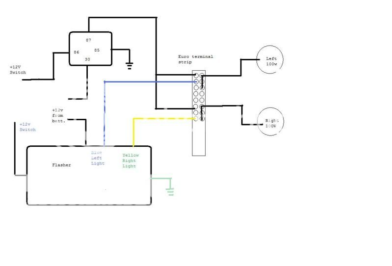
I just need to run the switch, and isolate using diodes, or a relay..
As for your question, I'll go with the wig wag being used more.. (best guess..)
Thanks!
Posted By: hotwaterwizard
Date Posted: February 26, 2011 at 3:42 AM
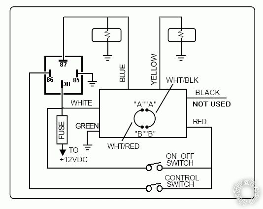
OKAY I read the instructions. They are a bit confusing.
It tells us that the flasher is disabled when the High Beam in the vehicle is turned on.
I simulated that with your relay idea. But I did not tie the 2 lights together the module will do that for you.
Then I put a normal switch to the relay to switch it on and off to enable and disable the flasher.
The other switch is an on off switch. You wouldn't want the lights on all the time would you?
------------- John DeRosa (Hotwaterwizard)
Stockton California
When in doubt, try it out !
Posted By: hotwaterwizard
Date Posted: February 26, 2011 at 4:18 AM
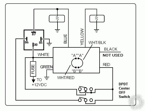
If you have to use 1 switch to control and turn it on and off you must have one with Center OFF
(ON OFF ON) Then wire it like this.
------------- John DeRosa (Hotwaterwizard)
Stockton California
When in doubt, try it out !
Posted By: jp523
Date Posted: February 28, 2011 at 12:04 AM
I just had an epiphany! While reading all the helpful posts, and looking at the wiring diagram for the "flasher", I noticed the "black" wire is for the highbeam override. So the way that I have the lights wired, I can use the red wire to flash, and the black wire for steady! I don't need the stock wiring harness for the lights.. Can't wait to wire these now!
Thanks!
|