special solenoid valve
Printed From: the12volt.com
Forum Name: Relays
Forum Discription: Relay Diagrams, SPDT Relays, SPST Relays, DPDT Relays, Latching Relays, etc.
URL: https://www.the12volt.com/installbay/forum_posts.asp?tid=126322
Printed Date: February 18, 2026 at 9:15 AM
Topic: special solenoid valve
Posted By: red86
Subject: special solenoid valve
Date Posted: February 26, 2011 at 12:14 PM
Hello,
I have a nitrous oxide system that I am adding an emergency shutoff valve system to. The valve does not require any constant current to keep it ON or OFF. Just a momentary 12v to either the ON circuit wire or OFF circuit wire. It has a 3rd wire which is the valve solenoid ground. I want to set it up so that the existing switched ON 12v arming circuit also produces a momentary 12v pulse that will activate the emergency valve to the ON position circuit wire and when the arming switch is turned OFF, another momentary 12v pulse is sent to the emergency valve OFF position circuit wire. The emergency shutoff valve is supplied with a momentary 2 way switch that I don't want to use to keep the installation clean. Per the mfg there is no need for a relay due to low current is used just to activate the valve from one state to the other. Anyone have any suggestions on how to accomplish this?
Thanks!
Replies:
Posted By: hotwaterwizard
Date Posted: February 26, 2011 at 8:14 PM
A diagram of your existing circuit would help.
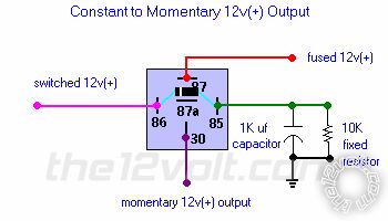
You may be able to use this circuit twice.
------------- John DeRosa (Hotwaterwizard)
Stockton California
When in doubt, try it out !
Posted By: red86
Date Posted: February 26, 2011 at 8:25 PM
Thanks for the reply.
That configuration would work for when the main arming switch is turned ON. It would produce the needed momentary voltage pulse to the valve solenoid ON circuit. The problem is when the main arming switch is turned OFF, I would need to produce a momentary voltage pulse to the valve solenoid OFF circuit. The valve has 3 wires: one for a momentary voltage to turn the valve ON, one for a momentary voltage to turn the valve OFF, and a ground.
Posted By: hotwaterwizard
Date Posted: February 27, 2011 at 12:28 AM
I don't understand your Question I guess???
------------- John DeRosa (Hotwaterwizard)
Stockton California
When in doubt, try it out !
Posted By: hotwaterwizard
Date Posted: February 27, 2011 at 12:42 AM
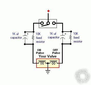
If we are dealing wit just pulses try this circuit,
------------- John DeRosa (Hotwaterwizard)
Stockton California
When in doubt, try it out !
Posted By: red86
Date Posted: February 27, 2011 at 7:49 AM
The ON circuit and the OFF circuit of the valve needs to be connected to the momentary 12v circuits. The arming switch currently is used just to turn the entire system ON and OFF. It is just that, an On and OFF switch. The valve is a completely separate component that I want to activate with the same switch. What I need is a separate momentary 12v pulse to activate the valve to the ON position when the arming switch is turned ON (main power ON) and a separate momentary 12v pulse to activate the valve to the OFF position when the arming switch is turned OFF (main power OFF). Arming the system and activating the valve are two totally different independent operations to be perfomed hopefully with the same switch. Unfortunately I am not familiar enough with this site to provide a schematic of the current setup but I hope this clears things up.
Thanks
Posted By: KPierson
Date Posted: February 27, 2011 at 8:44 AM
Do you have an electrical bottle opener?
-------------
Kevin Pierson
Posted By: red86
Date Posted: February 27, 2011 at 8:54 AM
No electric bottle opener. I spray a 300 shot so I have 2 10# bottles mounted in the rear. Individual bottle openers would be cost prohibitive. That is why I'm installing an emergency shutoff solenoid valve in the main line.
Posted By: oldspark
Date Posted: February 27, 2011 at 3:15 PM
No interlock on the above relay diagram? (Can both solenoids can be energised at the same time?) Run power for one thru the NC contact of the other if that is a concern.
Posted By: red86
Date Posted: February 27, 2011 at 3:47 PM
I did not post those relay diagrams. Hotwaterwizard posted those and based on what I see it was a nice try but does not do what I need it to do and is not a accurate representation of the component functionalities.
If you read my circuit description carefully you should understand exactly what I'm looking for. I need a momentary 12v pulse when my ON/OFF switch is turned ON for one circuit and another momentary 12v pulse when the ON/OFF switch is turned OFF for another circuit. The trick here is to get a momentary 12v pulse to the solenoid valve OFF circuit when the power is turned OFF at the switch.
Thanks
Posted By: KPierson
Date Posted: February 27, 2011 at 4:19 PM
HotWaterWizard is on the right track.
Use your master arm switch to control the coil of a SPDT automotive relay.
Tie Pin 30 to 12vdc
Pin 87 will go to a constant to momentary relay (like above) with the output being the "enable coil" of the valve
Pin 87A will go to a second constant to momentary relay with the output being the "disable coil" of the valve
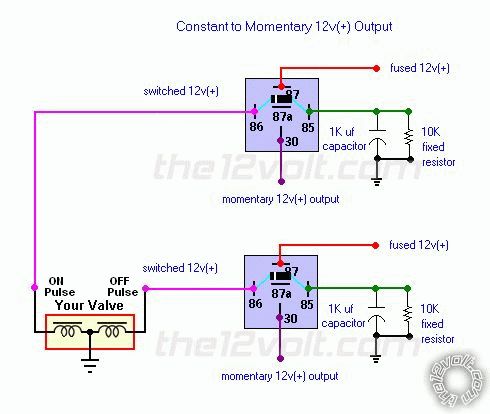
When you turn the switch on it will energize the relay which will send a constant voltage out pin 87. This constant voltage will get changed in to a pulse. When you turn the switch off, the relay will drop out, providing constant voltage on pin 87A. This constant voltage will get changed in to a pulse as well.
-------------
Kevin Pierson
Posted By: red86
Date Posted: February 27, 2011 at 4:31 PM
Kevin,
I think I understand your concept. It would be easier to visualize if it was drawn out. Any chance you could create a diagram showing what you are describing? It would be much appreciated. The mfg of the solenoid valve states that relays are not necessary due to needing only a monentary low current 12V to trigger the valve ON and OFF and the valve does not require any current to maintain either valve state. Seems like relays in the circuit would be overkill unless they are vital to creating the momentary pulsed 12v. Is there an easier way to do this?
Thanks!
Posted By: red86
Date Posted: February 27, 2011 at 5:03 PM
Kevin,
I think I got it. When I put it on paper it now makes sense.
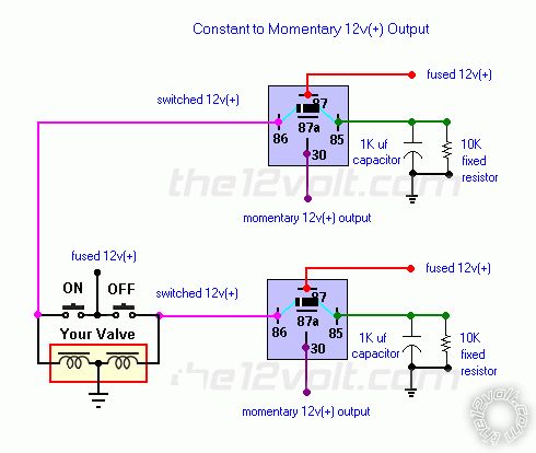
Master arming switch drives a SPDT master relay. Term 87 of the master relay drives constant to momentary relay # 1 for momentary ON signal to valve. When the master switch is OFF, term 87A of the master relay drives constant to momentary relay #2 for momentary OFF signal to valve.
Seems complicated but it should work. It still seems like since I don't need any current to maintain the valve position that this could be done an easier way. What do you think?
Thanks
Posted By: hotwaterwizard
Date Posted: February 28, 2011 at 11:37 PM
I will try again with another Idea I have along the same line.
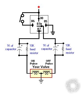
OKAY Why do we need a relay at all? a SPST Switch is it (ON/ON)
------------- John DeRosa (Hotwaterwizard)
Stockton California
When in doubt, try it out !
Posted By: red86
Date Posted: March 01, 2011 at 10:19 AM
The arming switch (ON/OFF) is already existing and I need to do everything with just one switch. The 1st drawing with the relay would work especially when there is no power from the switch in the OFF position. Relay 87A solves that problem. Will the resistor/cap combo change a constant into a pulse? If so for how long of a pulse? I probably need about a second.
Thanks
Posted By: hotwaterwizard
Date Posted: March 01, 2011 at 8:42 PM
That is the purpose of the resistor and Capacitor. To change it into a pulse. 
For a longer pulse just add another capacitor across the other in parallel  ------------- John DeRosa (Hotwaterwizard)
Stockton California
When in doubt, try it out !
Posted By: i am an idiot
Date Posted: March 01, 2011 at 9:39 PM
I do not think that the 10K resistor will provide enough current to operate the solenoid.
Posted By: hotwaterwizard
Date Posted: March 01, 2011 at 9:44 PM
Good question . I asummed it was simular to the Relay coil amp draw. the Capacitor actually powers the coil and the resistor drains the voltage down at a given rate depending on its value.
Imagine the capacitor as a battery. ------------- John DeRosa (Hotwaterwizard)
Stockton California
When in doubt, try it out !
Posted By: i am an idiot
Date Posted: March 01, 2011 at 10:11 PM
If the capacitor was paralleled across the Motor, it would make a pulse last longer. No DC voltage will go through the capacitor. The only voltage to get to the Motor will be the voltage allowed through the resistor.
Posted By: hotwaterwizard
Date Posted: March 01, 2011 at 10:44 PM
Posted By: i am an idiot
Date Posted: March 02, 2011 at 3:48 AM
In the diagram on the first link. The meter is shown across the capacitor. The voltage will ramp up just as described in the text and the graph. If the load were paralleled across the cap, and the load could be triggered with a 10K resistor in series with it, then yes it would act as a delay circuit. The coil of the relay would not energize until the voltage raised enough to energize the coil enough to pull the actuator. The 10K resistor is paralleled across the cap to discharge the cap between cycles. If you look at some of the delay relay circuits yo will notice that the resistor values are way lower than 10K. The circuit as drawn MAY power an LED, but nothing more.
Posted By: hotwaterwizard
Date Posted: March 02, 2011 at 8:24 PM
The first link does not say anything about Paralell circuits just series. Also AC acts different than DC. Now the second link does talk about Parallel RC Time Constants. Do your Math with that one.
In a nutshell what you are saying is that none of the12volt members know what they are talking about when they post these circuits that are varified by countless members all over the world. WE ARE NOT IDIOTS SIR. YOU ARE WRONG!!!!
https://www.the12volt.com/relays/page5.asp
https://www.the12volt.com/relays/relaydiagram22.html ------------- John DeRosa (Hotwaterwizard)
Stockton California
When in doubt, try it out !
|