latching master relay wiring
Printed From: the12volt.com
Forum Name: Relays
Forum Discription: Relay Diagrams, SPDT Relays, SPST Relays, DPDT Relays, Latching Relays, etc.
URL: https://www.the12volt.com/installbay/forum_posts.asp?tid=128686
Printed Date: May 07, 2026 at 4:10 AM
Topic: latching master relay wiring
Posted By: seattle_ice
Subject: latching master relay wiring
Date Posted: September 30, 2011 at 8:07 PM
I would appreciate some verification by more experienced auto wiring people as to the suitability of my wiring diagram.
What I have is a master latching solenoid (relay) for the whole car. I want to wire it so that a DPDT momentary(center-off) switch will switch the state, but will do nothing when you try to turn it on if it is already on, or off if it is already off.

Replies:
Posted By: oldspark
Date Posted: October 01, 2011 at 8:27 PM
Not that I'd recommend a relay for the whole car (unless with redundancy - ii, 2 relays), but why not use an ordinary relay as per:
Posted By: seattle_ice
Date Posted: October 02, 2011 at 2:26 AM
oldspark wrote:
Not that I'd recommend a relay for the whole car (unless with redundancy - ii, 2 relays), but why not use an ordinary relay as per:
Because the latching relay uses no current to maintain its state, so would not drain the battery over time while in storage, and is designed to handle 150+ amp loads.
Posted By: oldspark
Date Posted: October 02, 2011 at 7:38 AM
So why would you want the relay "ON" (ie, car connected) if in storage?
Granted, whilst on, an ordinary relay will take say 50mA - 200mA depending, but that is insignificant with the engine running else for short periods (maybe overnight etc).
Otherwise for a dual-coil latching relay, why not one push button for on & one for off?
PS - IMO there is no need to quote previous replies in full....
Posted By: i am an idiot
Date Posted: October 02, 2011 at 8:00 AM
Does the latching solenoid require reversing polarity to change states?
Posted By: Ween
Date Posted: October 02, 2011 at 1:23 PM
hi,
guessing the solenoid in question does require reversing polarity
to change states. solenoid of that type is often used in motor homes/coaches as a master disconnect.
m
Posted By: i am an idiot
Date Posted: October 02, 2011 at 1:36 PM
I did not fully inspect the diagram, but I did notice that T2 will never see positive voltage. Both legs of that pole of the switch are at ground.
Posted By: seattle_ice
Date Posted: October 02, 2011 at 2:51 PM
oldspark wrote:
So why would you want the relay "ON" (ie, car connected) if in storage?
Otherwise for a dual-coil latching relay, why not one push button for on & one for off?
It would be off for storage. I just don't want it draining power when it is on, but the car is not running.
A DPDT switch is essentially the same as two switches, so that is just semantics.
i am an idiot wrote:
Does the latching solenoid require reversing polarity to change states?
No, it does not. It simply flips every time it sees voltage, so it does not matter which of the T1/T2 legs gets positive and which gets negative.
Posted By: seattle_ice
Date Posted: October 02, 2011 at 4:27 PM
OK, after looking at that first diagram for a while it will not work. So I am starting from scratch to make this easier to understand.
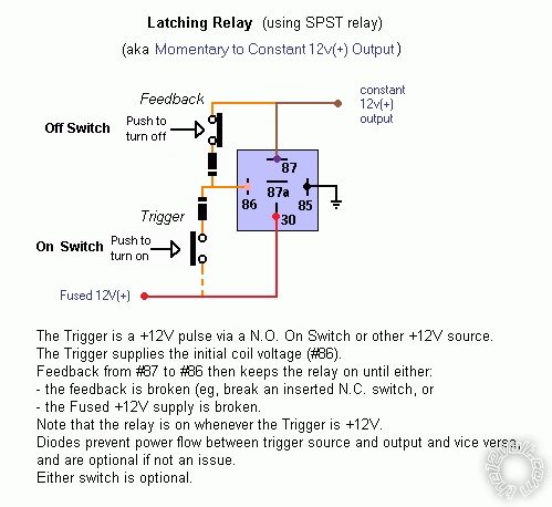
The following diagram is what I need except for one thing - If the power is on, and you push the switch to "ON", it will turn the power off. I want it do nothing.

Posted By: i am an idiot
Date Posted: October 02, 2011 at 4:42 PM
The above diagram will change state everytime you push switch to the left. If it is on, and you push the switch either direction, it will turn off. If it is off and you push switch to right, it will do nothing.
Posted By: seattle_ice
Date Posted: October 02, 2011 at 4:44 PM
i am an idiot wrote:
The above diagram will change state everytime you push switch to the left. If it is on, and you push the switch either direction, it will turn off. If it is off and you push switch to right, it will do nothing.
Yes, that is exactly what I said. I want to add/convert whatever to make the switch do nothing when pushed to the left (ON) when it is already on.
Posted By: i am an idiot
Date Posted: October 02, 2011 at 4:53 PM
I can not think of any way to do that without having a relay powered up while the solenoid has output.
Posted By: seattle_ice
Date Posted: October 02, 2011 at 5:06 PM
i am an idiot wrote:
I can not think of any way to do that without having a relay powered up while the solenoid has output.
Like this, right?

It seems like there would be a good way to do this with a latching relay so it would not take power to maintain, but I haven't figured it out.
Posted By: i am an idiot
Date Posted: October 02, 2011 at 6:04 PM
Your solenoid is latching. Is it that hard to see if it is on before you try to turn it on? Have you thought about an LED indicator? Minimal current draw when it is on.
Your above diagram should do the trick.
Posted By: seattle_ice
Date Posted: October 02, 2011 at 6:22 PM
i am an idiot wrote:
Your solenoid is latching. Is it that hard to see if it is on before you try to turn it on? Have you thought about an LED indicator? Minimal current draw when it is on.
Your above diagram should do the trick.
It is in a locked box in the trunk with the battery. The car has been shaved and I am going to use the unlock functions to pop the doors, and I wanted to be able to use the arm/disarm alarm outputs to turn the main power on and off. So I don't want to hit the arm button and have it turn on, or vice versa. It would also not be very convenient to have to check the state before you turn it on or off.
Posted By: seattle_ice
Date Posted: October 02, 2011 at 7:47 PM
I think this will work, it only grounds the coil of the relay when the momentary switch s pressed. I don't know if the changeover from one terminal to the other will be a problem.

Posted By: oldspark
Date Posted: October 02, 2011 at 8:02 PM
I take it that the latcher is a pulse type - ie, each +12V pulse swaps its state - as opposed to one that requires a coil polarity change.
In that case it is simply a push-button to swap. No relays except if it is an alarm etc to enable it. (The alarm being ties to battery +12V hence always presenting a drain irrespective of the latcher. Doesn't that contradict your aim?)
Connections from the relay's output seem meaningless.
Posted By: seattle_ice
Date Posted: October 02, 2011 at 8:08 PM
oldspark wrote:
I take it that the latcher is a pulse type - ie, each +12V pulse swaps its state - as opposed to one that requires a coil polarity change.
In that case it is simply a push-button to swap. No relays except if it is an alarm etc to enable it. (The alarm being ties to battery +12V hence always presenting a drain irrespective of the latcher. Doesn't that contradict your aim?)
Connections from the relay's output seem meaningless.
1. Yes, it is a simple pulse, polarity does not matter.
2. I am ok with the alarm draining the battery, as nothing else will be on at that time, and they are designed with that in mind. What I was trying to avoid was having the relay draining power when I don't turn the main power off while the car is parked in the garage, or any other place I park, or if I forget to set the alarm/cut off the power.
3. The relay's single output would only connect to the master relay if the power is not already on, and you push the switch to on. Any other combinations are ignored by the relay.
Posted By: seattle_ice
Date Posted: October 02, 2011 at 8:13 PM
To further illustrate #3 in the previous post:
When you push the switch to the left (on) position while the relay is not energized, the power would travel from M1, to the NC terminal on the relay, out the common terminal to the switch, and through the switch to T1 on the master solenoid. If the relay becomes energized due to there being +12v at M2 and the switch grounding the other side of the coil, the relay would be connected across the NO terminal, and nothing would happen.
Posted By: oldspark
Date Posted: October 02, 2011 at 9:02 PM
So it is for short term storage as well as long. (Physical isolation switches are best for long term; they handle the starter current as well.)
IMO it's the wrong relay for the purpose. You should have a dual-coil latcher, else a polarity changer (but that requires an extra relay in your case).
And lest hope it doesn't release whilst driving.
Posted By: seattle_ice
Date Posted: October 02, 2011 at 9:49 PM
oldspark wrote:
....IMO it's the wrong relay for the purpose. You should have a dual-coil latcher....
This was actually my first thought. This is the only one I have found that was made for Automotive purposes that will handle 150 amp switching and is tried and tested. It is just a modified starter solenoid.
A dual coil would have made solving the problem easier since you would have a dedicated on side and off side.
Posted By: seattle_ice
Date Posted: October 02, 2011 at 10:35 PM
After looking at all the information, and the advice offered here, I searched for a while and found a battery disconnect that requires reversing the polarity across the coil to change state. So if i is on, pushing on again will do nothing, and that solves the entire problem.
Thanks for all the help guys, back to working on my car....
Posted By: i am an idiot
Date Posted: October 02, 2011 at 10:56 PM
| Actuators / Reverse Polarity |
This is practically identical to the 5 wire alternating 12V(+) system above. The only difference is there's no switch! Both motor legs rest at ground at the relays. To lock or unlock the vehicle, polarity is changed on one motor leg.
 |
Posted By: seattle_ice
Date Posted: October 03, 2011 at 2:07 AM
Idiot: That would work on the new one that works by reversing polarity. But the one I have now would change state no matter which one you hit at any given time. So you could hit on twice and it would go on then off.
Posted By: oldspark
Date Posted: October 03, 2011 at 6:18 AM
Glad you found a new relay, and hopefully it is a latcher.
Your info....
seattle_ice wrote:
This ... was made for Automotive purposes that will handle 150 amp switching and is tried and tested. It is just a modified starter solenoid.
... had me worried. You don't just modify a starter relay and turn it into a latcher. Modifieds usually don't have zero current. And modifying an intermittent relay for long-term use...
But problem solved, so end of story.
Posted By: seattle_ice
Date Posted: October 03, 2011 at 1:56 PM
oldspark wrote:
Glad you found a new relay, and hopefully it is a latcher.
Your info....
seattle_ice wrote:
... It is just a modified starter solenoid.
... had me worried. You don't just modify a starter relay and turn it into a latcher. Modifieds usually don't have zero current. And modifying an intermittent relay for long-term use...
I simply meant that the manufacturer used the same casing and parts as a typical starter solenoid.
The new one is actually a heavy duty one made for RV use. It is rated for 200 amps continuous. And of course it is a latcher. If it wasn't that would defeat the entire purpose of what I was asking for.
Posted By: seattle_ice
Date Posted: October 12, 2011 at 3:19 PM
I have a final resolution, and it works very well. So I am posting it here for informational purposes.
The original relay I had would not work well, so I found one made for RV's.
Specs:
- It is rated for 100 amps continuous (you can get up to 200 if needed)
- Mechanical Latching Function (Magnetic)
- Reverse current to change state
After testing, I determined there was one aberrant behaviour - if it was off, and you applied current to turn it off again, it would be momentarily on while the current was applied. So I routed the power to the "Off" switch relay from the "On" side of the main latching relay, so if it was off and you tried to turn it off again, nothing would happen.

I wired it to use a SPDT momentary switch locked in the box with the alarm for testing/working purposes, and also use the alarm outputs.
Posted By: seattle_ice
Date Posted: October 19, 2011 at 6:43 PM
And here it is installed in the battery box (The right one is the starter solenoid, the left one is the one relevant to this thread):


|