side marker wiring
Printed From: the12volt.com
Forum Name: Relays
Forum Discription: Relay Diagrams, SPDT Relays, SPST Relays, DPDT Relays, Latching Relays, etc.
URL: https://www.the12volt.com/installbay/forum_posts.asp?tid=131318
Printed Date: January 17, 2026 at 6:28 AM
Topic: side marker wiring
Posted By: geraldcole
Subject: side marker wiring
Date Posted: April 30, 2012 at 8:01 PM
I have a 98 acura integra and I have a single filament side marker that I'm installing.
What I want to accomplish is having the side marker solid with the parking light and blink with the turn signal.
I do NOT want them to blink in sequence. I want to use relays so that the side marker and blinker blinks at the same time.
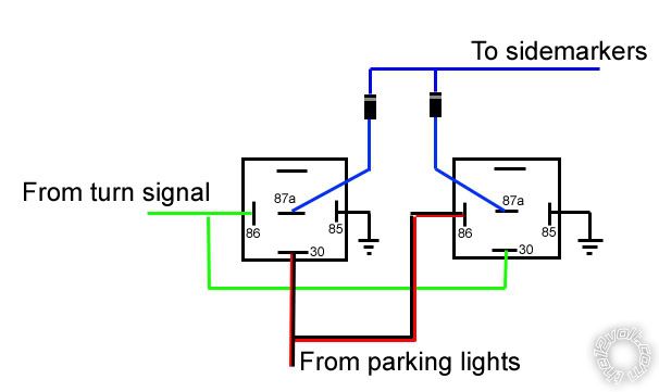
Here's how I have it wired right now (which is not working) for one side marker. The below diagram only allows the side marker to blink when the parking lights and the turn signal is on and it does nothing else.
Replies:
Posted By: howie ll
Date Posted: May 01, 2012 at 3:12 AM
Your right hand relay is wrong, it should be the same as the left, also the blue wires at 87a should be kept apart with no diodes.
-------------
Amateurs assume, don't test and have problems; pros test first. I am not a free install service.
Read the installation manual, do a search here or online for your vehicle wiring before posting.
Posted By: geraldcole
Date Posted: May 01, 2012 at 3:30 AM
The diagram i showed was for one side only. If i keep the two blue wires apart then at the side marker i would have those 2 blue wires and a ground there with only a single filament bulb. Also what would be the purpose of having 2 relays hooked up together doing exactly the same thing?
Posted By: oldspark
Date Posted: May 01, 2012 at 3:35 AM
Yep, that's a fun "problem".
It can be considered the same as a 'merkan flashing stop light (for indicators) or the old common use of rear indicators as reversing lights.
Each side required DPDT switching (actually 1 SPDT and 1 SPST), and the indicator switch was moved from it's normal before the left/right switch to a relay contact - the switch instead energised whichever side's relay.
Not that any flasher-can is involved in your case.
It can be simply achieved with a similar grounding trick as was done for your fogs (ie, off with high), but that will mean the sides flash out of phase with the front & rear main indicator bulbs.
And that grounding trick may not work if using LED lights...
I have been considering converting my side flashers to also be on as clearance lights, though with that came the thought of having it brighter for flashing (compared to being "non-painfully" bright as a mere parker/clearance light).
And having recently decided to (finally!) get into PICAXEs, I think that's the way to go - especially for the flasher & reverse or stop bulb combination. IMO it's much easier programming a PIC to control an SPDT relay than use a DPDT relay and relocate the flasher can.
I suspect the same PIC solution for the side clearance & flashers. (eg, an 8-pin "08" series PICAXE; ~$3-$4.)
But the above is just a fore-ramble.
I'll search for relevant diagrams that I have and get back to you.
Otherwise I'll actually have to think about the relay/wiring solution. (I once wrote a lovely 3-pager with figs and the theory etc only to later realise I had it totally R's about. Though I had installed a working 2 DPDT relay solution (for combined rear indicator & reversing lights), when it came to the writeup, I managed to confuse the lot again!)
Incidentally, a J-FET is perfect for this. It works by passing full current UNLESS there is a voltage to reduce or turn it off (aka to pinch it).
Unfortunately they are only low-current devices, nowhere near enough for bulbs (as required for traditional flasher cans).
However, maybe LEDs... hmmm?
Remind me if I don't get back to you (unless someone else posts a solution).
PS - which I think has now been posted...
Posted By: geraldcole
Date Posted: May 01, 2012 at 3:43 AM
The 3 situations that the sidemarker should be on are as follows:
Parking lights on: sidemarker solid
Turn signal on: sidemarker blinks at the same time
Parking lights on and turn signal on: sidemarker solid and blinks at the same time as turn signal
Posted By: geraldcole
Date Posted: May 01, 2012 at 3:54 AM
The sidemarkers are incandescent not leds so jfet wouldn't send enough juice as you said. And i want them to blink in phase. I don't understand how howie's suggestion would make it work, but with a little clarification with what should be at the sidemarker I can give it a go.
Posted By: geraldcole
Date Posted: May 01, 2012 at 4:05 AM
Grats on starting with picaxe controllers they are definitely out of my league [:)]
Posted By: howie ll
Date Posted: May 01, 2012 at 4:47 AM
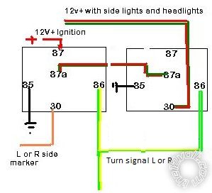
Here's one I just cooked up, Peter, go over it please but as far as I've worked it out,this will give you marker lights solid when lights are on and flashing with indicators when you use them.
With this diagram the side markers will work as required except when you use the hazard flashers.
You can change this by altering the ignition source wire going to 87 on the two left relays to a constant 15amp fuse, although I would start with a 20amp then work down.
I originally used an ignition source as it's safer.
The diodes (1N4004) are MANDATORY. It won't work properly (i.e. separate the sides) without them:-
side_markers.bmp------------- Amateurs assume, don't test and have problems; pros test first. I am not a free install service.
Read the installation manual, do a search here or online for your vehicle wiring before posting.
Posted By: geraldcole
Date Posted: May 01, 2012 at 7:36 AM
If I'm reading this right, your diagram could be done without the diodes if you use 2 relays on each side/each side marker (4 total) instead of 3 total. Below I've cropped your diagram to just show 2 relays which would equal just one side marker or one side.
I've currently hooked it up this way and the only thing that happens is when the running lights are on and you turn the signal on, then the side marker blinks. Otherwise the sidemarker does nothing.
Posted By: howie ll
Date Posted: May 01, 2012 at 7:42 AM
Side marker lights should be default wired in with the running (side) lights.
Cost of one relay = cost of 100+ diodes it's a no-brainer.
-------------
Amateurs assume, don't test and have problems; pros test first. I am not a free install service.
Read the installation manual, do a search here or online for your vehicle wiring before posting.
Posted By: geraldcole
Date Posted: May 01, 2012 at 7:49 AM
I did this merely to simplify it and so I could hook it up right now since I don't have the diodes yet. I'm hooking up the sidemarkers from scratch, since they did not come on the vehicle. So are you saying the sidemarker should have power from the running light on one end and then the 30 from Relay 1 running to the other side? If that's the case wouldn't it wink out of phase?
Posted By: howie ll
Date Posted: May 01, 2012 at 7:52 AM
You have to suck it and see, I'm guessing a half second delay.
-------------
Amateurs assume, don't test and have problems; pros test first. I am not a free install service.
Read the installation manual, do a search here or online for your vehicle wiring before posting.
Posted By: geraldcole
Date Posted: May 01, 2012 at 8:24 AM
Getting it to work out of phase is no problem, I could just tap into the turn signal and the parking lights, put a diode on each wire and plug them into the side marker.
It's getting it all to work in phase that I'm struggling with.
Posted By: geraldcole
Date Posted: May 01, 2012 at 3:43 PM
Still no luck I hooked it all up the way you described and the only time the side marker is engaged is when the turn signals is on and when the parking lights are on, Causing the side marker to blink and that's it.
Posted By: oldspark
Date Posted: May 04, 2012 at 2:54 AM
Sorry... I'm back.
The problem is it's a "time function" - ie, whilst blinking, the parker/DRL has to be held off.
That means that the "circuit" is still "on" in between the +12V blinker flashes.
Hence a hold circuit for about 1 second (assuming the usual 85 cpm (cycles/flashes per minute) which means that after the LAST flash, the side lamps will be held off for whatever the delay is before being re-powered by the parker or DRL etc circuit.
IMO that is quite okay, and in some ways "cool".
IMO the only practical or legal objection could be that a side gives an extra "off before on" which could be confusing if indicators are immediately changed to the other side. But I'd argue that from the front or rear, that side's main indicators won't, and from the side, it just means an extra (half) cycle which IMO errs on the side of safety/caution if anything.
So, in lieu of a diagram [POST EDIT - see below], per side needs an SPDT relay, a diode and a cap to provide the delay. A small cap if a transistor or FET is used...
The SPDT (changeover) relay is wired with output #30 to the side lamp +12V.
The normally closed input 87a is from the normal parker +12V (or DRLs etc).
The normally open input 87 is from the flasher signal to the main (front or rear) flasher lights.
Hence normally the parker etc signal powers the side lamps.
When our "delay circuit" energises the relay, it switches over so the side lamp(s) are lit by the flasher can.
Cool?
So, now the delay circuit.
Both methods below are "triggered" from the respective flasher circuit (ie, main flasher lamp wire) and require a diode to prevent the capacitor discharging thru the main bulbs.
The cap is sized so that the RC time constant provides the required delay of ~1 second or more. t = RC (though not quite if R is the relay...).
The "brute force" method:
Noting that the 10k resistor is not needed (I don't know why it is there unless it's for damping?).
And where #30 is to the side lamp (ie, " +12V output to Turning Lamps".
And #87 (labelled " fused +12V") is from the switched parker (or DRL etc) +12V.
And the unconnected #87a if from the flasher signal - ie, to the left of the left "input" diode.
The other method that uses a much smaller cap, has a more predictable time delay and overcomes relay chatter uses a transistor or MOSFET to turn on the relay.
EG - for a relay coil of about 100R (R = Ohm) resistance, C needs to be at least 10,000uF. I'd suggest a 25V 10,000uF which means an electrolytic which is polar, the volume of a cigarette packet, and not too robust (large, and dries out over time etc).
For a MOSFET, the delay is essentially any combination of R & C (similar to the image above) provided R isn't too high - eg, a 1uF cap with a 1MR resistor or 0.1uF with a 10M-Ohm (much smaller than a 10,000uF cap!).
In both cases the RC is an approximation to the "actual" switch off delay - that depends on the relay or transistor or FET's switch-off voltage. But if not long enough, increase the cap (or increase R) in proportion to the increase required.
Also, a smaller relay with lower coil resistance could be used, but the st'd 30A type automotive relays are attractive for their abundancy and easy connection (spades etc).
Incidentally, the above time-delay is the "add on" method for rear flasher with stop/reverse lights instead if needing to re-plumb flasher can and switch, but I have various arguments against it for main lighting.
Posted By: itsyuk
Date Posted: May 06, 2012 at 11:43 PM
why use relays?
what if you just diode isotated the turn signal wire AND the park light wire into the side marker power wire.....BUT also series some sort of resistor in the park wire. then the bulb would be dim when park was on but always flash full stregth for turn signal....
you would just ground the other side marker light wire. ------------- yuk
quiet rural missouri, near KC.
If your system moves you physically and not emotionally, you have wasted your money.
Posted By: oldspark
Date Posted: May 07, 2012 at 1:02 AM
Yep - that's quite valid if full & dim is okay for flashing and parkers.
The delay & relay is for totally off between flashes.
Posted By: howie ll
Date Posted: May 07, 2012 at 3:25 AM
Itsyuk, already suggested that in my second diagram but as Oldspark said the OP wants the side (running?) lights to flash in sequence so I had to use a cut out indicator switched relay hence loads of diodes.
-------------
Amateurs assume, don't test and have problems; pros test first. I am not a free install service.
Read the installation manual, do a search here or online for your vehicle wiring before posting.
Posted By: oldspark
Date Posted: May 07, 2012 at 3:37 AM
itsyuk's is in phase.
It is the simplest implementation where the "normal" side-lamp power is via a resistor (and diode) so it's dimmer.
The flasher is connected via a diode that bypasses the resistor, hence flashing the side lamp at full brightness (less diode drop).
But in between flashes if the side lamp was/is on, it will only dim instead of full-off is the timer/relay was used.
I think it's the best solution. No relay, no cap.
But if full-off is desired between flashes even when the "side lights" are on, then the delay & rely type circuit is required.
Posted By: howie ll
Date Posted: May 07, 2012 at 4:09 AM
This but in this scenario the resister is going to cook. Wouldn't a DC-DC unit be better?
:- E23_other_side_marker.bmp------------- Amateurs assume, don't test and have problems; pros test first. I am not a free install service.
Read the installation manual, do a search here or online for your vehicle wiring before posting.
Posted By: oldspark
Date Posted: May 07, 2012 at 6:12 AM
I meant one resistor per side (so that the other side doesn't also partly flash).
The resistor would only cook if undersized. I was assuming a 3W bulb etc, hence maybe a 22 to 33 Ohm 2W resistor...
Posted By: itsyuk
Date Posted: May 07, 2012 at 12:07 PM
what if the "resistor" was just another bulb hidden in series with the park light wire?
-------------
yuk
quiet rural missouri, near KC.
If your system moves you physically and not emotionally, you have wasted your money.
Posted By: oldspark
Date Posted: May 07, 2012 at 4:33 PM
Yep - that was to be one of my suggestions...
That means under 1/2 brightness for park lights.
And that's one (extra) bulb for each side AFTER the diode.
|