delay relay pin out needed
Printed From: the12volt.comForum Name: Relays
Forum Discription: Relay Diagrams, SPDT Relays, SPST Relays, DPDT Relays, Latching Relays, etc.
URL: https://www.the12volt.com/installbay/forum_posts.asp?tid=137349
Printed Date: April 29, 2024 at 12:29 AM
Topic: delay relay pin out needed
Posted By: 2therock
Subject: delay relay pin out needed
Date Posted: September 29, 2014 at 1:03 AM
Hi Folks,
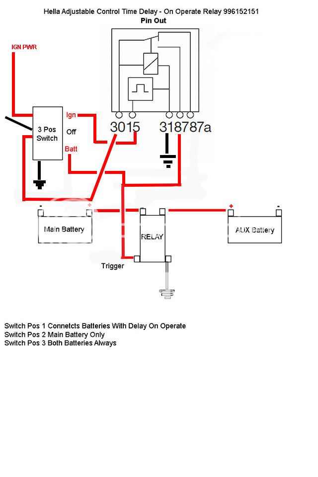
I need help with wiring this Hella Delay On Operate Relay for a dual battery setup on a three position switch.
I want:
Ignition Position - Triggers the AUX Battery Contact Relay after a delay so when I start the engine it will be on the main battery only and then connect the AUX battery after the delay.
Off Position - Main Battery Only, No AUX Battery Contact Relay trigger.
Battery Position - Triggers the AUX Battery Contact Relay with Ignition Off (or on)
Replies:
Posted By: 2therock
Date Posted: September 29, 2014 at 1:09 AM
OK, My image did not show.
I'll try again.

I'll try again.
Posted By: 2therock
Date Posted: September 29, 2014 at 1:13 AM
Posted By: oldspark
Date Posted: September 29, 2014 at 1:26 AM
See texasindustrialelectric.com/relays_996152151.asp.
#15 is to the +12V on signal (IGN) and the others are normal; #31 is GND.
But that's only a 10A relay which is probably not enough for an aux battery bigger than ~7AH - especially if AGM.
And you have not shown the 2 fuses requires in your circuit (unless the batteries are colocated). Actually I suggest self resetting circuit breakers - definitely if up to 50A inclusive - they're only ~$10 each.
But I'd suggest a proper battery isolator - eg, search "oldspark uibi" for a chargeLight controlled isolator, else use typical voltage controlled aka smart isolators. (Use them to switch a bigger relay if needed.)
Posted By: 2therock
Date Posted: September 29, 2014 at 9:47 AM
Thank You,
Ooop! Sorry, I hope you say that because I did not indicate the time delay-on-operate relay is to supply 12v to the bigger relay that requires:
7.5v minimum to pull it in.
3.0v Minimum to hold it in.
Coil has 7.7 Ohms or resistance.
Here is a Link to the Coil Then choose the "Sales Bulletin" link to see the specs.
I'm doing this so not to jam both batteries in at start-up, and will most likely set the timer up for 900 seconds(15 minutes)to let the main recover and charge alone for a while and then let them combine.
The on position will be the default.
The off position will be to dictate separation for whatever reason arrives at the time of choosing it. Such as jumping off a stranded motorist from the AUX.
The on all the time would be for if the main was dead and I could jump myself off.
Believe me I am no where close to being an electrician so fire away if needed.
Here is what my pipe dream is below.
Posted By: 2therock
Date Posted: September 29, 2014 at 10:19 AM
In case you guys have viewed this before 11L:16 PM EST, I have made revisions. Please refresh browser.
Thanks for your patience.
Thanks for your patience.
Posted By: oldspark
Date Posted: September 29, 2014 at 10:34 AM
Firstly leave 87a unconnected. It's the 30 to 87 connection you want.
Secondly a fuse or breaker at each link end near each battery. (IE - TWO fuses in total to protect the interlink cabling & relay and batteries.)
Thirdly I wouldn't worry about the delay other than to ensure enough time to crank and start.
Of course if you leave the IGN on for a while, or the engine stalls and you don't turn off IGN before cranking...
The best isolator is generally the alternator charge-light controlled type. Failing that, a voltage controlled aka smart type, but one of their disadvantages is their turn on delay - usually between 15 to 60 seconds.
IMO recovering maximum TOTAL charge quickly is best, hence connect all batteries as soon as the alternator begins to charge.
There are those that claim connecting 2 batteries is dangerous - ie, if one if quite flat, the current/spark/shock is supposedly an issue.
Mind you those same people often use voltage-controlled isolators (maybe they believe their priority charging bullsh?!) so instead of connecting a mere (say) 12.6V main battery to a flat secondary, they fully charge their main battery and THEN connect it AND the >14V alternator with more reserve capacity to the secondary battery...
Consider using a UIBI instead (my name for the chargeLight controlled isolator), or even an MW728 that coincidentally I wrote about in an other thread today. Though the MW728 reconnects at 12.5V, that can be increased by using a diode in its GND else +12V supply. (The diode would have to be a 2A or 3A type to handle the 14V/7.7R = 1.8A of the isolator's coil.)
Then you don't have to worry about time delays etc. (The MW728 has a 15 second turn on delay as I recall.)
Posted By: 2therock
Date Posted: September 29, 2014 at 11:21 AM
Thanks!,
Getting ready to go to work but will leave with these questions.
*Firstly leave 87a unconnected. It's the 30 to 87 connection you want. *
If I connected 87a as shown and switched to position 3, would this give me my desired scenario of manually triggering without the timer?
*Secondly a fuse or breaker at each link end near each battery. (IE - TWO fuses in total to protect the interlink cabling & relay and batteries.) *
Please recommend or link me to fuse types and ratings?
Thank You
Posted By: oldspark
Date Posted: September 29, 2014 at 4:53 PM
87a (NC) is connected (to 30) when the relay is "off" (de-energised).
87 (NO) is connected (to 30) when the relay is "on" (energised).
IOW your batteries will always be interconnected (except for milliseconds as the relay switches between the 2). That is not what you want.
NC & NO designate the Normally Closed & Open contacts where "Normally" refers to unpowered - ie, as in a box on the shelf.
Fuse ratings - no higher than the lowest of the interlink cable or relay or connector rating, but can be lower to limit or protect the battery.
Fuse types - since I presume you are ]i]linking way more than 50A (and hence cheap self resetting breakers), I'd recommend ANL or whatever bolted "single piece" type suits. Not glass types.
BTW, since you're using a high current isolator (I'd assume 200-400A), why not connect the 2 batteries during cranking? If you need "dip free" independence, fine, but otherwise is helps main battery life.
IOW a mere ignition controlled relay with a off switch. Just don't forget to turn off ignition else disable the relay. (Maybe use my push button latching relay to switch the isolators "high" 2A current - tun on ignition and hit one button to engage; it turn off with IGN off of whenever the off button is pushed.)
Posted By: 2therock
Date Posted: September 30, 2014 at 12:36 AM
Thanks For Your Patience........
I see it now. My cake and eat it too of switching between 87 & 87a is not cake.
So I need a Toggle Switch that will feed from two different sources.
From IGN power to the delay relay
From the Main BATT to the Isolator trigger.
The reason I want to delay is from the philosophy Cole Hersee uses in their 48530 Smart Battery Isolator 200A.
"It reduces the load on the charging system by not connecting the auxiliary battery until the primary battery is charged to 13.2V. This extends the life of expensive charging components."
It seems you have a different it look on it and I'm listening believe me.
So when I fire up the main will recover and then the AUX is online.
The reason I do not go with the Cole Hersee unit is it does not have the manual user control options I want, and has a parasitic drain of 5mA to 8mA. The darned thing is always ON!
You say its better for the battery without the delay, they say better for the ALT with. Which ever way I go I can tweak the timer to suit.
The vehicle typically will sit idle for 7 to 10 days, some times more and sometimes away from home or where I can attach a maintainer.
From the factory it already has a 50mA drain after everything finally sleeps. 50mA is the max to tolerate as I'm told.
So with key off and the toggle in the 1 or 2 position the AUX does not take any parasitic hit.
So what about this picture? And here is the vehicle in question.
Posted By: oldspark
Date Posted: September 30, 2014 at 3:03 AM
Ah yes... The Cole Hersee "excuse" is the marketing used by all voltage controlled isolator sellers to turn a disadvantageous necessity into something that seems like a benefit. It has also been called a "priority charging system" which is ok if that means a simple time delay where the main battery gets all available alternator capacity (as if for some reason it is limited), however saying that "(it) monitors the main battery and connects the aux battery when the main if full" is quite fallacious and is misleading advertising, as well as in most cases something totally unnecessary - ie, why delay the charging of the aux battery - isn't it better to get both recharged as quickly as possible?
IMO any alternator that can't handle its own output is somewhat pathetic. I maintain that properly designed alternators are self limiting (ie, reach (magnetic) saturation that prevents overcurrent and have sufficient cooling to handle their max output). Some don't - I have often written about Bosch alternators from at least the 1980s & 1990s that can't even handle jump starts nor weak batteries whereas the typical Japanese alternators from the 1960s onwards that I have dealt with have no such problems - except by exception.
BTW - That (Cole Hersee) statement "not connecting the auxiliary battery until the primary battery is charged to 13.2V" is crap. What they mean is they do not connect the aux battery until the "system" (ie, alternator/battery) reaches 13.2V; they do not monitor the voltage of the main battery itself.
And since most charging systems go straight to 14V or higher after starting, the aux battery connects immediately - except that their required "delay to connect" means the aux won't be connected until after that delay passes.
I'm surprised anyone still includes such a misleading statement. (We have Laws against that, tho it requires someone to point out the mislead to the relevant authorities.)
All voltage sensing types will have some parasitic drain. They monitor voltage full-time so their sensing circuitry is always powered and sensing. (An IGN +12V input would overcome that.)
The lowest standby aka parasitic load I know of is 50uA or 500uA with LED status indicator for the Oatley Electronics 12-24V Dual Battery Controller K227 kit (was AUD$22; may now be discontinued) which uses a 80A rated latching relay and hence no extra current except when changing relay state. (Since rediscovering the UIBI I now use the K227 as a battery protector - ie, a low voltage cutout - the same as a battery isolator but with a lower voltage set point.)
To overcome the parasitic drain of a voltage sensing isolator you could power the sensing circuity from IGN +12V - maybe from the ECU relay (if fitted) if the IGN +12V has a high voltage drop. The voltage difference between IGN +12V and actual battery voltage should not be significant wrt to isolator sensing - it's not as critical as an alternator's (regulator's) sensing which should be within (say) 0.1V or 0.2V if the battery's actual voltage.
Some voltage sensing isolator are of integral construction but many are simply relays/contactors with sensing circuity attached and the sensing +12V from the heavy +12V relay input can easily be intercepted.
Of course the isolator's GND can also be intercepted (unless it is integral and not wired and is via its case to body/chassis).
Both intercepts may have to handle the full current of the relay coil (maybe 2A for large 200A - 400A relays/contactors) plus the sensing circuity - the latter should only be its standby current - eg, 5mA to 8mA plus a bit extra; else maybe allow for 100mA.
I'll get back to you on switching arrangements, and maybe how the almighty UIBI can do it.
BTW, I think BlueSea (amongst others) have manual bypass variants, however I still maintain that voltage sensing isolators are inferior to alternator charge light controlled isolators (eg, the UIBI) and their only place (with a few rare exceptions) is where such charging or not charging (charge light) circuits do not exist - eg, stator or permanent magnet alternator as on some bikes & RVs, marine systems, etc.
Posted By: 2therock
Date Posted: September 30, 2014 at 9:56 AM
Thank You Sir,
Your words here are falling on some VERY appreciating and grateful ears.
I knew I there was more I didn't like the Cole Hersee Isolator.
I needed that.
I had already ordered the delay-on-relay before my post and still like something about having the default option being truck fire up on the Main alone and then the AUX joining in so I may perhaps just shorten the delay.
Perhaps this short delay would provide me with confirmation the Main is healthy enough to start her up alone, rather than a carte blanche combined. Good to know after a while of idleness. A 2005 with only 70k miles should indicate she gets lots of rest eh?
FYI my alternator is the OE 145A two wire variety. I remember for the 2005 trucks they advertized how it was a part of an MPG helper because it senses the demand and provides as needed giving less drag when providing less.
Fusing? I have read a so-called rule of thumb would be to match the alternator output. I'm going with the ANL type and may start with 125A or 150A.
Other than some kind of mishap, I am the type to gladly aid a motorist who needs a jump. With this setup I would switch to the middle (my true isolation position) and use the AUX + and Frame or Block -. With that in mind what rate would you start with.
Thanks, Waiting on your words on switching. I work evenings and my replies are either in the AM on either side of my downtime. Zzzz..
Posted By: oldspark
Date Posted: October 02, 2014 at 3:17 AM
I thought I forgot something this morning (ie, this thread).
There is 2 wire and then there is 2 wire...
Traditional alternators had at least a charge light output with optional Sense &/or Ignition wires (eg, SIL types) tho most are single wire (D+) else 2-wire (S&L aka S & D+). (Ignition should be superfluous due to the D+/L connection, but they had their reasons.)
Modern alternators however can be DP types and other name types that I've forgotten.
These are somewhat different in that they are ECU interactive (the ECU provides the chargeLight info tho that could be via LCD & text etc via the CAN) however one of the lines can be used as an L-type trigger...
Maybe if I explain UIBI development. The UIBI (now Mark-1) was simply a traditional electric fuel pump etc relay or battery isolator (relay) that was turned on when the alternator was charging - ie, D+/L = +12V and not GND as it is when the chargeLight is lit.
UIBI-1 functioned well with old electro-mechanical voltage regulators that used a relay for the D+/L circuit but those e-mags were replaced by electronic regulators.
Initially electronic voltage regulators also handled the typical 250mA relay/UIBI current because they were designed to be compatible with existing wiring - ie, multiple lamps driven by D+/L (most early IGN-on "dash lamp tests" where via a diode-isolated connection to the D+/L circuit) else cars with fuel cutoffs or electric chokes or fuel pump relays.
Later vehicles started using more sophisticated methods for controlling such functions - eg, ECU's handled fuel pumps & cutoff valves; dash circuits handled lamp test functions (ie, other than the chargeLight they would not come on after an engine stall whereas D+/L diode-connected lamps would).
Hence alternators no longer had to sink (ground) heavyish loads (like 250mA bulbs) nor supply 250mA etc relays. Not that heavy sinking electronic D+/L circuits had to source equivalent +12V currents, but many did.
Anyhow, along came the UIBI-2 with was merely a MOSFET buffer with RC filtering that drove the (UIBI) relay. Hence the UIBI was a mere nano-Amp or micro-Amp loading on the D+/L circuit.
The RC delay was also sufficient to enable use on DP type (ECU controlled or interactive) alternators (and high impedance enough not to effect existing circuits).
But the UIBI-2 was scrapped in favor if the UIBI-3 which used a PICAXE 08M2 as a front end. It too had burger-all loading on D+/L circuits and wasn't much more expensive than the UIBI-2 (eg, $5 plus UIBI-2 costs).
And it was envisaged to be a universal battery isolator that could handle older and new ECU type alternators and offer User-configurable connection delays or manual override options, and probably an alarm to notify of link failures or out-of-spec batteries etc.
Later it was decided to (eventually...) also incorporate a "smart battery isolator" option - ie, voltage controlled so that the UIBI-3 could be used on any alternator/generator system.
Of course its smart isolator parameters would be fully user configurable - eg connect voltage, disconnect voltage, reconnect delays (though probably set to a minimum of 15 secs unless other smarts prevented excessive hunting or switch cycling).
The UIBI-3 was essentially a universal piece of hardware that could be user configurable and handle any alternator type, and any functional (software) updates handle via download. (Eventually even real time text logs or alpha-numeric display/PC output.)
Alas the procrastinating else otherwise distracted and unnamed OldFart involved only got as far as the prototype UIBI-2 despite sourcing 08M2s several years ago...
As for fusing, the alternator-battery fuse is NOT to protect the alternator. It is (or should be) close to the battery and is to protect the battery and wiring in case of a short to GND.
In my experience, fuses do little to protect alternators, especially those too pathetic to handle being jumpstarted etc. [ I know of several old (small) alternators that tolerated modern-alternator-destroying (big) faults despite having no fusing at all! ]
[ FYI - The destructive current transients involved blow the main rectifiers and fuses are too slow to react. And as I said, alternators should be self limiting wrt to sustained (and short) overloads. ]
Hence IMO the alt-batt fuse should have nothing to do with alternator sizing and merely be sized to protect the cable, else lower if the cable capacity is far in excess of battery capabilities and alternator current demands.
And yet again I'll get back to you on that UIBI etc manual control stuff. (My router crashed last night just after submitting my reply above. I suspect my verbiage crashed it...)
When jump starting I jump from the battery +12V terminal, and usually the batt -ve terminal. That's because its the battery that usually supplies at least of the high current used for cranking.
Only if voltage drops are high might I jump from the alternator output (if accessible) and engine block, however I have often jumpered direct to the engine block and starter heavy +12V terminal of the flat vehicle. (IMO demonstrating the high voltage drops of starter and GND cables in OEM vehicles during cranking.) With the latter usually an engine-off jump straight from the battery is all that's required, but sometimes I'll run my engine to pre-charge the flat battery on non-Jap alternatored vehicles etc, or provide extra spark for some voltage sensitive ignition systems. (Both my starter and ignition function well at a mere 5V battery voltage, but others often still don't have the exceptional abilities my mere 49 year old vehicle has .)
.)
There is 2 wire and then there is 2 wire...
Traditional alternators had at least a charge light output with optional Sense &/or Ignition wires (eg, SIL types) tho most are single wire (D+) else 2-wire (S&L aka S & D+). (Ignition should be superfluous due to the D+/L connection, but they had their reasons.)
Modern alternators however can be DP types and other name types that I've forgotten.
These are somewhat different in that they are ECU interactive (the ECU provides the chargeLight info tho that could be via LCD & text etc via the CAN) however one of the lines can be used as an L-type trigger...
Maybe if I explain UIBI development. The UIBI (now Mark-1) was simply a traditional electric fuel pump etc relay or battery isolator (relay) that was turned on when the alternator was charging - ie, D+/L = +12V and not GND as it is when the chargeLight is lit.
UIBI-1 functioned well with old electro-mechanical voltage regulators that used a relay for the D+/L circuit but those e-mags were replaced by electronic regulators.
Initially electronic voltage regulators also handled the typical 250mA relay/UIBI current because they were designed to be compatible with existing wiring - ie, multiple lamps driven by D+/L (most early IGN-on "dash lamp tests" where via a diode-isolated connection to the D+/L circuit) else cars with fuel cutoffs or electric chokes or fuel pump relays.
Later vehicles started using more sophisticated methods for controlling such functions - eg, ECU's handled fuel pumps & cutoff valves; dash circuits handled lamp test functions (ie, other than the chargeLight they would not come on after an engine stall whereas D+/L diode-connected lamps would).
Hence alternators no longer had to sink (ground) heavyish loads (like 250mA bulbs) nor supply 250mA etc relays. Not that heavy sinking electronic D+/L circuits had to source equivalent +12V currents, but many did.
Anyhow, along came the UIBI-2 with was merely a MOSFET buffer with RC filtering that drove the (UIBI) relay. Hence the UIBI was a mere nano-Amp or micro-Amp loading on the D+/L circuit.
The RC delay was also sufficient to enable use on DP type (ECU controlled or interactive) alternators (and high impedance enough not to effect existing circuits).
But the UIBI-2 was scrapped in favor if the UIBI-3 which used a PICAXE 08M2 as a front end. It too had burger-all loading on D+/L circuits and wasn't much more expensive than the UIBI-2 (eg, $5 plus UIBI-2 costs).
And it was envisaged to be a universal battery isolator that could handle older and new ECU type alternators and offer User-configurable connection delays or manual override options, and probably an alarm to notify of link failures or out-of-spec batteries etc.
Later it was decided to (eventually...) also incorporate a "smart battery isolator" option - ie, voltage controlled so that the UIBI-3 could be used on any alternator/generator system.
Of course its smart isolator parameters would be fully user configurable - eg connect voltage, disconnect voltage, reconnect delays (though probably set to a minimum of 15 secs unless other smarts prevented excessive hunting or switch cycling).
The UIBI-3 was essentially a universal piece of hardware that could be user configurable and handle any alternator type, and any functional (software) updates handle via download. (Eventually even real time text logs or alpha-numeric display/PC output.)
Alas the procrastinating else otherwise distracted and unnamed OldFart involved only got as far as the prototype UIBI-2 despite sourcing 08M2s several years ago...
As for fusing, the alternator-battery fuse is NOT to protect the alternator. It is (or should be) close to the battery and is to protect the battery and wiring in case of a short to GND.
In my experience, fuses do little to protect alternators, especially those too pathetic to handle being jumpstarted etc. [ I know of several old (small) alternators that tolerated modern-alternator-destroying (big) faults despite having no fusing at all! ]
[ FYI - The destructive current transients involved blow the main rectifiers and fuses are too slow to react. And as I said, alternators should be self limiting wrt to sustained (and short) overloads. ]
Hence IMO the alt-batt fuse should have nothing to do with alternator sizing and merely be sized to protect the cable, else lower if the cable capacity is far in excess of battery capabilities and alternator current demands.
And yet again I'll get back to you on that UIBI etc manual control stuff. (My router crashed last night just after submitting my reply above. I suspect my verbiage crashed it...)
When jump starting I jump from the battery +12V terminal, and usually the batt -ve terminal. That's because its the battery that usually supplies at least of the high current used for cranking.
Only if voltage drops are high might I jump from the alternator output (if accessible) and engine block, however I have often jumpered direct to the engine block and starter heavy +12V terminal of the flat vehicle. (IMO demonstrating the high voltage drops of starter and GND cables in OEM vehicles during cranking.) With the latter usually an engine-off jump straight from the battery is all that's required, but sometimes I'll run my engine to pre-charge the flat battery on non-Jap alternatored vehicles etc, or provide extra spark for some voltage sensitive ignition systems. (Both my starter and ignition function well at a mere 5V battery voltage, but others often still don't have the exceptional abilities my mere 49 year old vehicle has
.)Posted By: oldspark
Date Posted: October 02, 2014 at 5:21 AM
Well I thought there was a more modern copy...
The pic below is ~5 years old - and I have permission to use it for the12volt.
And note that the Battery symbol is shown incorrectly - namely inverted - the +12V terminal should be a LONG line and its negative/GND a short line segment. (Stupid diagram drawers!!)
It may look overly complicated but please note:
- maybe I should have posted a "simple" UIBI diagram first...,
- the pic refers to "Fuel Pump Relay" wiring and control but it's exactly the same as the UIBI or alternator chargeLight controlled battery isolator... merely substitute UIBI or battery isolator (relay) for Fuel Pump Relay; the 2nd battery's +12V terminal instead of the Fuel Pump on relay terminal #30; and the +12V input (#87) as the main battery's +12V terminal.
The pic endeavors to show how extra +12V control inputs are simply added by diode-isolating all the +12V inputs to relay coil.
It does NOT show an override disable switch which would be an NC (Normally Closed) switch for the relay coil - eg, between #85 & GND, or between #86 and the rest of the (diode) sources.
Note that for any input to override the manual OFF NC override switch, simply move its diode output to AFTER the NC off switch - ie, between the OFF switch coil #86. (The NC OFF switch therefore cannot be in the #85 to GND segment UNLESS the override is a GND signal in which case reverse the diode IF backfeed from the NC grounding OFF switch is not desired.)
To explain...
Ignore the starter motor and its upper two horizontal links and Start switch position.
Ignore all diodes and lines other than the Charge Lamp and lowest Alt-Regulator charge lamp controller switch and the RH FPR relay coil.
Hence is should be a "simple":
- battery +12V thru Ignition Switch (IGN) to Charge Lamp +ve,
- the lower regulator switch which is the D+ or L aka chargeLamp terminal to the isolator (FPR's) relay coil #86.
Assume IGN is off. There is no +12V to the chargeLamp and the alternator's (voltage regulator's) D+/L terminal is at GND and hence the relay is de-energised and the batteries are isolated (30 & 87 are open as shown in the diagram).
Turn IGN on. +12V is applied to the top of the chargeLamp and it illuminates because its bottom is switched to GND via the alternator's D+/L switch/circuit. But the isolator relay is still off because its #86 is GND via the D+/L switch/circuit.
Crank the engine. The charge light should remain off (tho I have met a few exceptions) hence the batteries are still isolated.
The engine starts and the alternator produces output. Internally its voltage generation switches D+/L to +12V.
Hence:
+12V on both sides of the chargeLight extinguishes the Charge Lamp (ie, there is zero volts across it),
that +12V energised the relay coil and hence closes 30 & 87 thereby interconnecting the batteries.
Stalling the engine causes D+/L to revert to GND as does turning off the IGNition, hence the battery isolator relay opens and isolates the battery.
Simple eh?
 ??
??
So in summary, +12V to the isolation relay's coil #86 closes the relay and connects the batteries.
That +12V comes from the alternator when it is charging.
[ FYI from a Fuel Pump POV - ignore this block if not iterested...
You may see the brilliance of the circuit. The fuel pump operates ONLY when the alternator is charging. Hence if the engine stalls (after hitting an accident) the fuel pump immediately shuts down.
Of course a fuel pump also requires a prime function to pressurise fuel injectors before cranking or supply carby & injector fuel during cranking. That can be done with an SPST (4 pin) Fuel Pump Relay by diode combining a +12V cranking signal with D+/L, or using an SPDT (changeover) relay with its NC 87a terminal connected to a +12V cranking signal - eg, from the starter solenoid input to have enough current to directly power the fuel pump - hence why the fuel pump is shown on $30 and IGN or battery +12V on #87. otherwise #30 & #87 are interchangeable {if, in this case, 87a is unused}. ]
To add other or manual inputs to interconnect the batteries, insert a diode in the D+/L circuit and add (parallel) all other +12V control sources via diodes to relay coil #86 as shown in the diagram.
One such input could be an HU's remote output tho it should be disableable if the HU is on when the alternator is not charging (maybe thru a switch enabling another relay to connect or disconnect the remote +12V).
A timer could also be inserted between D+/L and the relay coil.
So many possibilities...
And at the time (circa 2005) essentially such battery isolator (or fuel pump) control was available on every vehicle via the chargeLight circuit. The only issue was if D+/L could drive the relay.
[ Solutions there included using an intermediate smaller relay - eg, a 1kOhm coiled relay (<15mA coil current) similar to how your 10A timed relay buffers your BIG relay's ~2A coil current; or a transistor or MOSFET buffer. ]
Yet people often bought the more expensive voltage aka smart battery isolators. I won't go into the operational disadvantages of those tho I have mentioned a few. And I won't go into the insanity of using oil pressure to control fuel pumps (why risk far worse damage to an engine than the lack of oil might do?) - I've discussed that enough elsewhere!
I think I've answered all your questions tho protection (fuse) and cable sizing are generalisations since details like battery type and application (load size & type - amps or winches etc) are lacking (AFAIRecall).
Plus a whole lot more info...
I'd like to say "but don't trust me; look around" however I know the plethora of bullsh and well meaning but flawed logic or misconceptions out there.
But you seem to have understood what I've said and hence understand such marketing or info crap. Of course maybe I'm just a good con artist - probably out to enhance my ego else make a fortune by providing all this free info.
However I welcome any knowledgeable person that has alternate info or views AND can reasonably argue such (no motherhood statements or generalisations and no attempts at personal assassination etc) in case it's not obvious to me, and I challenge any others to substantiate their case (tho I'll bail out to IMO obvious time wasters).
BTW - another brilliance with this circuit wrt to both battery isolation and fuel pump control is that if the alternator fails and hence does not energise the relay, to enable the fuel pump OR parallel the batteries (for enough juice to get home), simply disconnect the alternator D+/L (and S & I etc) and the chargeLamp should provide enough current to energise the relay (especially in older vehicles with D+/L tested dash lights).
(For newer vehicles you might need to jumper #30 to #87 direct, else #86 to +12V (IGN +12V, or the isolator input (#87 else #30), etc).
Also the D+/L GND/+12V changeover circuit is depicted as a 2-way switch. In old e-mag regulators it was essentially an SPDT relay. Later electronic and alternator-intergral voltage regulators often used SPDT relays else circuits that imitated SPDT relay behavior (allbethey maybe only capable of maybe 500mA to a few Amps) but even later alternators may have had lower D+/L current capability and possible negligible current capability when +12V.
But that D+/L switch is a good way of depicting traditional D+/L circuits. However it should be disregarded for newer ECU-interactive alternators - some filter or integrator and buffer is needed for their typical pulse output signalling (hence RC MOSFET etc buffers).
Another short reply ends...

The pic below is ~5 years old - and I have permission to use it for the12volt.
And note that the Battery symbol is shown incorrectly - namely inverted - the +12V terminal should be a LONG line and its negative/GND a short line segment. (Stupid diagram drawers!!)
It may look overly complicated but please note:
- maybe I should have posted a "simple" UIBI diagram first...,
- the pic refers to "Fuel Pump Relay" wiring and control but it's exactly the same as the UIBI or alternator chargeLight controlled battery isolator... merely substitute UIBI or battery isolator (relay) for Fuel Pump Relay; the 2nd battery's +12V terminal instead of the Fuel Pump on relay terminal #30; and the +12V input (#87) as the main battery's +12V terminal.
The pic endeavors to show how extra +12V control inputs are simply added by diode-isolating all the +12V inputs to relay coil.
It does NOT show an override disable switch which would be an NC (Normally Closed) switch for the relay coil - eg, between #85 & GND, or between #86 and the rest of the (diode) sources.
Note that for any input to override the manual OFF NC override switch, simply move its diode output to AFTER the NC off switch - ie, between the OFF switch coil #86. (The NC OFF switch therefore cannot be in the #85 to GND segment UNLESS the override is a GND signal in which case reverse the diode IF backfeed from the NC grounding OFF switch is not desired.)
To explain...
Ignore the starter motor and its upper two horizontal links and Start switch position.
Ignore all diodes and lines other than the Charge Lamp and lowest Alt-Regulator charge lamp controller switch and the RH FPR relay coil.
Hence is should be a "simple":
- battery +12V thru Ignition Switch (IGN) to Charge Lamp +ve,
- the lower regulator switch which is the D+ or L aka chargeLamp terminal to the isolator (FPR's) relay coil #86.
Assume IGN is off. There is no +12V to the chargeLamp and the alternator's (voltage regulator's) D+/L terminal is at GND and hence the relay is de-energised and the batteries are isolated (30 & 87 are open as shown in the diagram).
Turn IGN on. +12V is applied to the top of the chargeLamp and it illuminates because its bottom is switched to GND via the alternator's D+/L switch/circuit. But the isolator relay is still off because its #86 is GND via the D+/L switch/circuit.
Crank the engine. The charge light should remain off (tho I have met a few exceptions) hence the batteries are still isolated.
The engine starts and the alternator produces output. Internally its voltage generation switches D+/L to +12V.
Hence:
+12V on both sides of the chargeLight extinguishes the Charge Lamp (ie, there is zero volts across it),
that +12V energised the relay coil and hence closes 30 & 87 thereby interconnecting the batteries.
Stalling the engine causes D+/L to revert to GND as does turning off the IGNition, hence the battery isolator relay opens and isolates the battery.
Simple eh?
??
So in summary, +12V to the isolation relay's coil #86 closes the relay and connects the batteries.
That +12V comes from the alternator when it is charging.
[ FYI from a Fuel Pump POV - ignore this block if not iterested...
You may see the brilliance of the circuit. The fuel pump operates ONLY when the alternator is charging. Hence if the engine stalls (after hitting an accident) the fuel pump immediately shuts down.
Of course a fuel pump also requires a prime function to pressurise fuel injectors before cranking or supply carby & injector fuel during cranking. That can be done with an SPST (4 pin) Fuel Pump Relay by diode combining a +12V cranking signal with D+/L, or using an SPDT (changeover) relay with its NC 87a terminal connected to a +12V cranking signal - eg, from the starter solenoid input to have enough current to directly power the fuel pump - hence why the fuel pump is shown on $30 and IGN or battery +12V on #87. otherwise #30 & #87 are interchangeable {if, in this case, 87a is unused}. ]
To add other or manual inputs to interconnect the batteries, insert a diode in the D+/L circuit and add (parallel) all other +12V control sources via diodes to relay coil #86 as shown in the diagram.
One such input could be an HU's remote output tho it should be disableable if the HU is on when the alternator is not charging (maybe thru a switch enabling another relay to connect or disconnect the remote +12V).
A timer could also be inserted between D+/L and the relay coil.
So many possibilities...
And at the time (circa 2005) essentially such battery isolator (or fuel pump) control was available on every vehicle via the chargeLight circuit. The only issue was if D+/L could drive the relay.
[ Solutions there included using an intermediate smaller relay - eg, a 1kOhm coiled relay (<15mA coil current) similar to how your 10A timed relay buffers your BIG relay's ~2A coil current; or a transistor or MOSFET buffer. ]
Yet people often bought the more expensive voltage aka smart battery isolators. I won't go into the operational disadvantages of those tho I have mentioned a few. And I won't go into the insanity of using oil pressure to control fuel pumps (why risk far worse damage to an engine than the lack of oil might do?) - I've discussed that enough elsewhere!
I think I've answered all your questions tho protection (fuse) and cable sizing are generalisations since details like battery type and application (load size & type - amps or winches etc) are lacking (AFAIRecall).
Plus a whole lot more info...
I'd like to say "but don't trust me; look around" however I know the plethora of bullsh and well meaning but flawed logic or misconceptions out there.
But you seem to have understood what I've said and hence understand such marketing or info crap. Of course maybe I'm just a good con artist - probably out to enhance my ego else make a fortune by providing all this free info.
However I welcome any knowledgeable person that has alternate info or views AND can reasonably argue such (no motherhood statements or generalisations and no attempts at personal assassination etc) in case it's not obvious to me, and I challenge any others to substantiate their case (tho I'll bail out to IMO obvious time wasters).
BTW - another brilliance with this circuit wrt to both battery isolation and fuel pump control is that if the alternator fails and hence does not energise the relay, to enable the fuel pump OR parallel the batteries (for enough juice to get home), simply disconnect the alternator D+/L (and S & I etc) and the chargeLamp should provide enough current to energise the relay (especially in older vehicles with D+/L tested dash lights).
(For newer vehicles you might need to jumper #30 to #87 direct, else #86 to +12V (IGN +12V, or the isolator input (#87 else #30), etc).
Also the D+/L GND/+12V changeover circuit is depicted as a 2-way switch. In old e-mag regulators it was essentially an SPDT relay. Later electronic and alternator-intergral voltage regulators often used SPDT relays else circuits that imitated SPDT relay behavior (allbethey maybe only capable of maybe 500mA to a few Amps) but even later alternators may have had lower D+/L current capability and possible negligible current capability when +12V.
But that D+/L switch is a good way of depicting traditional D+/L circuits. However it should be disregarded for newer ECU-interactive alternators - some filter or integrator and buffer is needed for their typical pulse output signalling (hence RC MOSFET etc buffers).
Another short reply ends...
Posted By: 2therock
Date Posted: October 05, 2014 at 10:53 PM
Mercy, I'm floored, Thanks!
I have been doing some of the hardware work. I am waiting for the DPDT toggle to arrive.
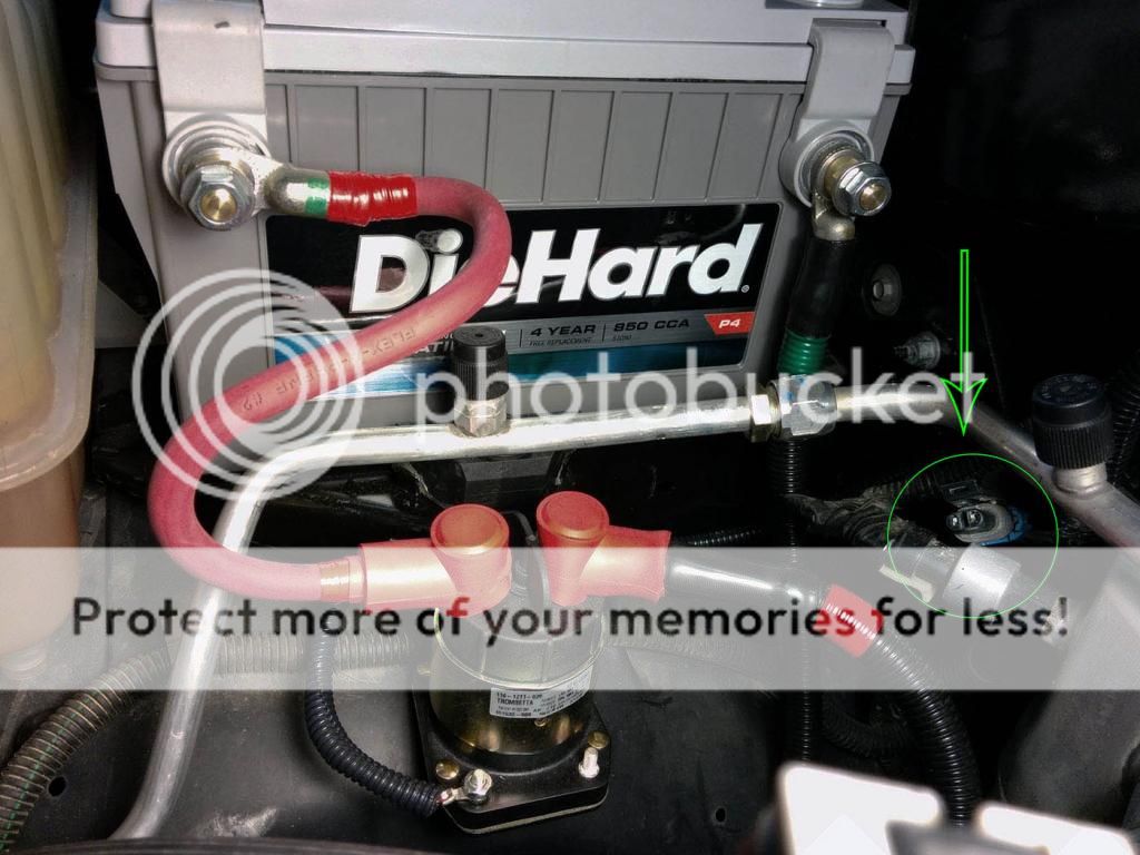
Below is a first pass install. I ran out of heat shrink and looming. The looming is High Temp non-split type.
The uncovered wire looks like its touching the HVAC line but is not. And its the first pass since I'm waiting on a fuse holder to arrive.
So........... I already have the Time-on-delay relay, and need a relay anyways so it will be used in the setup.
As for making use of the delay-on function usage let me ask this.
My parasitic drain as shipped from the factory is 47 - 50ma after everything goes into sleep about 1 hour later. In this hour she will be 90ma for 30 minutes, 74ma for the remaining 30 minutes.
The vehicle can sit for as much as 7 to 10 days. With this drain I'm sure a single AGM in good shape can handle it. "Gulp" -I hope! A DieHard Platinum AKA - Odyssey PC1500DT.
Do you know the formula for estimating the total drain for 240 hours of a 50ma drain, and an estimate for my 145A alternator to supply my truck in normal driving and top off the battery?
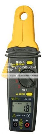
Also below is my GTC CM100 DC Ammeter. Great device for the poor man with good resolution and accuracy. There is a good review of it up on U Tube somewhere.
Thanks Again
My DC Amp Meter
Forward Progress
The circle and arrow is an unused connector I found lurking in the shadows. This was to show a buddy of mine. Its ign-on.
I have been doing some of the hardware work. I am waiting for the DPDT toggle to arrive.
Below is a first pass install. I ran out of heat shrink and looming. The looming is High Temp non-split type.
The uncovered wire looks like its touching the HVAC line but is not. And its the first pass since I'm waiting on a fuse holder to arrive.
So........... I already have the Time-on-delay relay, and need a relay anyways so it will be used in the setup.
As for making use of the delay-on function usage let me ask this.
My parasitic drain as shipped from the factory is 47 - 50ma after everything goes into sleep about 1 hour later. In this hour she will be 90ma for 30 minutes, 74ma for the remaining 30 minutes.
The vehicle can sit for as much as 7 to 10 days. With this drain I'm sure a single AGM in good shape can handle it. "Gulp" -I hope! A DieHard Platinum AKA - Odyssey PC1500DT.
Do you know the formula for estimating the total drain for 240 hours of a 50ma drain, and an estimate for my 145A alternator to supply my truck in normal driving and top off the battery?
Also below is my GTC CM100 DC Ammeter. Great device for the poor man with good resolution and accuracy. There is a good review of it up on U Tube somewhere.
Thanks Again
My DC Amp Meter
Forward Progress
The circle and arrow is an unused connector I found lurking in the shadows. This was to show a buddy of mine. Its ign-on.
Posted By: oldspark
Date Posted: October 05, 2014 at 11:51 PM
Total drain for 240 hours of a 50ma drain = 240 x 0.05 = 12AH.
The AH capacity of your battery over 240 hours (C240) will be much higher than its rating (which will probably be at C10 or C20) but using its rated capacity will give more conservative figures (ie, predict a lower battery voltage than it actually will be). [So assuming 70AH rating; 12AH means nearly 20% discharged.]
I don't know what you mean re the alternator, but size isn't important as long as there is capacity to spare. Charge rate is determined by alternator voltage, the internal battery voltage & its internal plus charging path resistance.
But generally speaking, most automotive batteries have recovered ~90-95% of their lost charge within 2-10 minutes.
Posted By: 2therock
Date Posted: October 06, 2014 at 12:54 AM
Thanks Again
Nominal Capacity: (20 Hr Rate-Ah 68) (10 Hr Rate-Ah 62)
Reserve Capacity Minutes: 135
Nominal Capacity: (20 Hr Rate-Ah 68) (10 Hr Rate-Ah 62)
Reserve Capacity Minutes: 135
Posted By: oldspark
Date Posted: October 06, 2014 at 1:48 AM
Yeah - probably about 100Ah @ C240...
But the good thing at such low discharge rates is that the terminal voltage will be so close to the OC (Open Circuit) (& rested) voltage measurement that SOC (State Of Charge) can be easily determined.
Just remember that terminal voltages after a recharge are invalid (surface charge has to dissipate....).
You may have read my various recommendation for a 3-digit dash voltmeter - I consider it mandatory; especially for us that modify or run accessories - it's the best indication of system health and even prewarns of over- or under-charging or a failing battery. (There's been 2 recent ammeter threads where I may have said more.) I have one direct to my battery terminals which is connected to +12V via a (small PCB) relay controlled by the Ignition +12V. (I might eventually add my intended 3-way switch to select IGN, off or +12V (full time) tho I also intended a smart circuit (PICAXE 08M2) to hold on for (say) 2 minutes after IGN off; maybe make "fulltime" a momentary switch else limited to 2 minutes, and maybe even switch it on (if off) and alter me if the system is out of spec.) But that has prevented a few embarrassing moments (like forgetting to reconnect the ammeter after various works)!
BTW - I'd suggest insulating the hot output from the battery. A big AGM like that probably has a short circuit current in excess of 3,000A and that's not a pretty sight. (Interrupting those currents is itself a hazard!)
Posted By: 2therock
Date Posted: October 13, 2014 at 1:09 AM
Hi,
Still tweaking the install. No toggle switch yet, just key on with the delay on operate in the mix. I think I see why you are not excited about that. It doesn't seem to make much of a difference.
I need some help with the toggle though. These are some really nice little units with bi-color LED's in the lever tips. But.......
The LED circuit needs resistors or ballast resistors or something to that effect.
I need help with what components to buy and a little guidance in the connections.
They are NKK M2100 series LED Tipped toggles.
Here is a link to the pdf sheet. https://www.nkkswitches.com/pdf/M2100.pdf
Look at the bottom of page A79 for the little section called "LED Colors & Specifications."
I sure would like to make it work for me. My Ign-on is 12v and peaks @ 1.6A when activated. I guess I need to reduce things for the LED Circuit.
Thanks.
Posted By: oldspark
Date Posted: October 13, 2014 at 3:19 AM
It's not so much that I'm not excited about battery isolator delays, it's more that I reckon it is (almost) complete bullsh.
To paraphrase, voltage sensing isolators (smart isolators etc) must have a delay before they connect. This is a disadvantage but smart isolator sellers turned it into an advantage by spouting crap like priority charging etc, and those that have invested in such relatively expensive isolators or read their blurb believe the hype and then add that piece of (bullsh) expert advice whenever they can.
The only time such a delay is of advantage is if you have (IMO) a crap alternator - ie, something that blows as a result of short trm overloads. But even crap alternators usually handle a 2nd battery unless perhaps lights & wipers are also on.
But from the POV of fastest total (re)charge recovery or the need to limit charge currents or the dangers of connecting a flat battery the delay is undesirable.
For the switch LEDs, a 560 Ohm resistor should be fine except RED / green = 1.2k Ohm. 1/2W resistors are fine; even 1/4W.
Posted By: 2therock
Date Posted: October 13, 2014 at 9:37 AM
oldspark wrote:
For the switch LEDs, a 560 Ohm resistor should be fine except RED / green = 1.2k Ohm. 1/2W resistors are fine; even 1/4W.
Thanks, I still need a little hand holding.
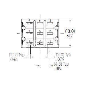
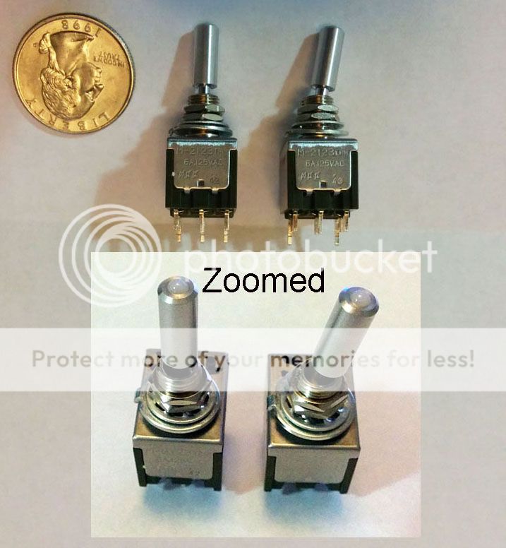
Below is a pic of the switch pins. 7, 8, & 9 are the LED pins, there is no 8 if it is a single colored or "Isolated" switch vs. the Asynchronous Bi-Color which I think I need.
So.... where or how would you terminate the resistors. And if you think I'll need an isolated switch please advise?
I would be super grateful for your help on this especially if you give me a complete schematic.
These are some nice little switches. I confess I found out the hard way and blew the LED's out of one in my ignorance of the separate circuit.
Fix me up and I'll send you a sample if you wish. I have seen them on a dash and very small, the LED is not too bright for night time, short throw, very classy.
Posted By: 2therock
Date Posted: October 13, 2014 at 9:51 AM
A picture of the switches.
Posted By: oldspark
Date Posted: October 18, 2014 at 6:53 PM
The LED wiring is shown on page A79 of M2100.pdf. It depends on what switch is chosen.
The resistor would be connected to the "common" of bi-color LEDs. (If different resistors are required for each LED, the larger could be used for both at their common terminal else each resistor to its LED.)
For single color LEDs, the resistor can be on either side assuming they are independent of the switching. (Many lit switches have bulbs/LEDs connected to switch terminals.)
Posted By: 2therock
Date Posted: October 19, 2014 at 9:28 AM
OK,
Still in the dark but taking a shot.
Going with Isolated bi-color switch M2122 (No Terminal No.8).
I see what looks to me as a two diodes jumped across 7 & 9?
What are the jagged arrows?
I drew the jumper, is it as simple as that, a single resister/diode jumper?
I am not an electrician and cannot make much of a secure feeling from the schematic where to connect anything since I already blew the LED out of a $12.00 switch.
I need help on what to connect to each pin.
Posted By: oldspark
Date Posted: October 19, 2014 at 11:31 AM
Ok, so 10mA for the bi-color RED / Green with a maximum of 25mA.
So for 14V, V=IR => R=12/0.01 = 1.2k. (Allowing to a 2V drop across the LED.) P=VI = 12V x 0.01A = 0.12W hence 1.2k Ohm 1/2W else 1/4W resistors.
Note that you need TWO resistors - each from the Common with one to +12V & the other to GND (0V).
The other end goes to your switch output. Hence - assuming the output when OFF is effectively GND - when the output is +12V, the current flows thru the red LED and via the 1.2k resistor to GND. When the output is OFF, the common side's +12V flows thru the other 1.2k resistor and green LED to GND.
"Effective GND" means the ability to ground the (green) LED's current - ie, 10mA.
If switching a relay that should be no problem. (Did I mention the UIBI?) (LOL)
If that is a problem - eg, if switching a low power or electronic circuit - then being an SPDT switch the centre could go to the load (output) and its inputs to +12V & GND respectively. (I hope that makes sense.) If the load cannot tolerate GND then a diode is required (eg, assuming less than 1A, a 1N400x diode in series with the (centre/common) switch output with line towards the load).
Posted By: 2therock
Date Posted: October 19, 2014 at 1:03 PM
Thanks,
I guess I'll have to find a local pro because all that is french to me. I think you give me too much credit.
I need to paint by the numbers on this one. The below is what I mean by needing a hand holding.
Put the position 1 device line in on 3
Put the position 1 device line out on 1
Put the position 3 device line in on 6
Put the position 3 device line out on 4
Position 2 is an off position
Attach one end of a xxΩ/xxW resistor(s)to ?
Attach the other end(s) to ?
If you get my drift. Heck, I would not even know how to pick out the resister off the shelf or catalog.
Thanks For Your Time
Posted By: oldspark
Date Posted: October 19, 2014 at 4:48 PM
Ok, so Isolated bi-color M2122.
May as well assume possible switching of output to GND (in case load/output doe not have sufficiently low resistance to pass LED current).
Input +12V to terminal 1 (else 3)
Output is from terminal 2.
The output (2) is also jumpered to (9) which is the + for the red & -/GND for the green LEDs.
(7) has two 1200 Ohm 1/2 Watt or 1/4W resistors. One goes to +12V (ie, to 1 (else 3) and the other to GND.
Hence the red LED will illuminate when the output is +12V.
The green should illuminate when the output (2) is grounded - ie, (2) to (1) is OPEN and the load is connected thus grounding (2).
If the green does not illuminate (assuming you have +12V to (1) or wherever you have connected one of the 1200 Ohm resistors to +12V) then connect GND to the other contact - ie (3). Then the output (2) will either be +12V from (1) else 0V/GND from (3).
I hope I'm not confused - the sun's up & I have yet to get to bed.
Just ensure you never short +12V to GND - ie, neither should be connected to (2) or (5) if the other is connected to 1, 3, 4, or 6.
BTW - you can swap terminals 4, 5 & 6 for 1, 2 & 3 respectively. (Hence link/jumper (9) to (5) instead of to (2).)
Posted By: 2therock
Date Posted: October 19, 2014 at 7:09 PM
Thanks!
I was feeling anxiety on the outlook on this one.
I have an electrician friend I will put this in front of for reinforcements and get back here.
It could be a while but not too long.
I am also adding some large - vintage Cibie 275S driving lights to the truck and we have a handle on that one.
This ties in with the project. I don't want the AUX lamps on with the high-beam trigger unless the AUX battery is connected.
Thanks for hanging in here with me and bailing me out.
Posted By: oldspark
Date Posted: October 20, 2014 at 5:59 AM
I'll sell you my Cibie Bi-Oscars. Bought for rallying decades ago but never used. (I bought them secondhand but essentially unused - maybe 30 minutes of use. And don't stress - they are compatible with heteros and others. )
A universal upgrade on my ancient vehicles is an upgrade to halogen lights. (Coincidentally Cibie; 5-3/4" types; inner spots and outer hi/low with integral park light.)
The inner spots have always run via relays - traditionally "New Era" dual relay types.
More recently (2 decades ago?) I started running outer lows & highs thru relays. Initially one relay per filament (as per my inner spots) but recently reduced to one relay per beam - ie, 3 relays for lo, high & spots - but I'll go back to one relay per filament - probably using micro (DIN) relays.
Tho individual relays is in part for redundancy, I find then invaluable for headlight alignment. (I can't get behind the lights to the connectors without removing the shells etc.)
The wiring is excessively oversized from the battery +12V. 2 runs - one for spots & one for hi/lo, each thru bolted plastic finks (fuse links) of about 60A rating. Each relay has its own 20A or 30A ATS type auto-resetting circuit breaker; they'll be (say) 10A or 15A when I move back to a relay-per-filament implementation. (Isn't it insane - using fuses for lights? In retrospect they should obviously be self-resetting breakers. To think my 1960s vehicles used a single 30A glass fuse for ALL lighting!)
Except for now - a temporary vehicle I got for 12 months )whilst reworking my then road goer) which is now in its 15th year of road registration - I've always had a switch for the spots to disable them on high beam. Smart bottoms that don't dip their lights after my first flash get the additional spots on their second flash (which for some reason is often quite a long despite their quick dip reaction).
And I'll only use outer highs around town. Reflected road signs are too bright with the spots anyhow.
Tho originally not fitting a spot-disable switch due to the vehicles temporary nature, when enduring reality hit I decided to use mode switching. That would have features like town or country (high with no spots or with spots) or anger (see country mode); permanent outer lows with inner "hibeam" spots; and flash selectivity - ie, flash low beams if beams are off (so as to not be fines for flashing {certain warnings} using hi beams, else hi with beams on, or spots in high-beam city/town mode.
It would also handle PWMing (dimming) of my 10W or 20W halogen parking bulbs to meet legal requirements, turn each off if its corresponding beam was operating, or dim a low or high filament to act as a parker if a parking bulb failed. Dimming of all bulbs to legal requirements - ie 55W lows - I currently use 90W/130W H4s and 100W spots. (Hibeam Wattage limits are somewhat ambiguous.)
Auto turn off if left on after say 60 seconds to get to the house or tent, or if battery voltage is low.
There were other features that I don't now recall, but all that was based on using PICAXE 08M2s which I've only had for a few years (or decades?) and thus have not had time to implement. Besides, an 08M2 to sense my OEM temp gauge to control my electric fan is a higher priority. (I've only been using electric fans since 1978 and thus haven't had time to build a temp sensing circuit, tho I did uses Klixons (temperature switches) a few years ago, but they kept falling off the head.)
Sorry, I seem to have digressed... 
I was going to say that you shouldn't have to disable lights because of a 2nd battery, the alternator should handle it. If not I'd also consider OFF if the aircon or wipers are on, the latter however possibly being when you want the extra lighting.
Besides, assuming a reasonable link and normal electrical loads, secondary batteries should be close to fully recharged within 10 minutes if not sooner.
But what I do suggest is a dash or condole voltmeter - specifically a 3-digit digital type. IMO they - else voltage monitoring alarms - should be standard equipment the same way ammeters were once considered essential.
I've written more than enough on that elsewhere - recently I think there were two the12volt threads regarding ammeters - but in short (no pun), a voltmeter can indicate a failing or undersized charging system, overvoltage (which kils batteries and other things), the state of the battery (aging or failing) or other faults - eg, failing starter motors.
Note that the voltmeter should be connected across the battery terminals because that is what the charging system is geared for. I use a small PCB type relay to connect battery +ve to the voltmeter when IGN is on. (The PICAXE 08M2 project to provide auto turn on under alarm conditions or on demand or 'hold-on' for 2 minutes after IGN off has been delayed due to unforeseen procrastination.)
Modern 12V vehicles should charge at say 14.2V - 14.4V. (Older 13.8V vehicles should be adjusted to 14.2-14.4V.)
Excluding faults, that voltage might drop at low RPM - especially with lights & wipers etc - but otherwise a drop means excess load on the alternator.
Of course my (Jap) alternator sits steady on 14.2V as soon as the engine starts - even at idle with spots (200W) and hibeam (260W) and wipers and brake lights and HU at an applicable start-up thrash volume tho it can drop to maybe 13.7 - 13.9V after some driving. [That's ok. The upto 14.4V is to help restore the battery (reverse any sulfation etc)) and charging voltages may (should!) vary with battery temperature (typically alternators use an internal temp sensor else a timing algorithm). And once fully charged, a 12V lead-acid battery's charge voltage should be reduced to its 'float voltage' (typically ~13.4V - 13.8V) tho car batteries seem to last fine without such features.]
Anyhow, with a voltmeter you soon get used to normal aberrations like low-RPM hi-load dips, brake or headlight dips, cranking dips to 10V or lower, and a fully charged battery of 12.7V dipping to maybe 12.5V or 12.3V when IGN or lights are on. (That's due to a battery's internal resistance - the voltage drop is proportional to the load (current) [V=IR] - even tho the battery is still 12.7V internally.
You then know if secondary batteries or lights or stereo volume cause excessive draw or that the alternator is failing etc.
WRT to battery condition there are probably 4 basics to know.
(1) A fully charged 12V lead-acid (whether wet/flooded cell, AGM or gel) should be ~12.7V. (In theory 12.67V at 25C, but that can vary with the battery type & construction. Refer to the battery datasheets.)
(2) After charging a battery will have 'surface charge' which may take up to 24 hours to self dissipate in wet cells. This means a voltage higher than what the actual battery is (wrt to its SOC = State Of Charge). My 14.2V charged car battery can read 13.7V immediately after engine switch off. (If I wanted to know its real SOC I'd have to dissipate the surface charge - eg a few to 15 minutes with lights or hibeam, or wait up to one day.)
Rats, what were the other 2? The "not above 14.4V (long term) because excess gassing occurs" & that it kills AGMs (because they have no fluid to gas or boil) was ancillary. So too the "need above ye olde 13.8V" due to newer chemistry AND because 13.8V was insufficient to reverse the plate sulfation that increasingly occurs the more 'not fully charged' a battery is.
Maybe that as a Rule Of Thumb, assume each 0.1V drop/change is equivalent to a 10% change in State Of Charge - ie, remaining capacity. [Usually it's more like 1.2V or 1.4V per 10% SOC - eg, if full is 12.7V and 0% SOC (fully flat) is 11.3V; sometimes less (0% = 11.9V for some batteries), but 0.1V is usually conservative and an easy to use figure to use. EG - you shouldn't discharge a deep cycle battery more than 50%, hence 5 x 0.1V = 0.5V from say 12.6V (or 12.7V) = 12.1V so if the battery is 12.1 or 12.2V its ok (but should be charged ASAP). The actual 50% SOC voltage might be 12.0V for a 12.65 100% SOC (fully charged) and 11.45V 0% SOC deep cycle, but our 12.1 (or 12.2V) is a conservative estimate.
Or that a battery's capacity increases with temperature (hence heat a flat battery in emergency conditions) but its life reduces.
FYI - the latter is a detail used by some car-audio forums. A long gone OP on the12volt intended placing his 2nd AGM battery in the engine bay to increase its capacity. (I won't name the relevant Florida based forum.) I thought that was brilliant - gaining maybe 20% to 30% capacity by reducing the battery's life 4- or 8-fold (each 10C temperature rise halves battery life) whilst also increasing its internal resistance which increases with temperatue (and state of discharge and they buy AGMs for their lower internal resistance) instead of buying a third battery and placing both in the boot/trunk thereby gaining 100% extra capacity at half their (individual) resistance with lower stress per battery for under half or one quarter the ongoing cost. Ah yes, I see amazing things on the web!
Anyhow, I'll go and collect my thoughts.
Besides Agents of Shield is about to start and I need to shower all my neighbor's 4WD grime off first.
A universal upgrade on my ancient vehicles is an upgrade to halogen lights. (Coincidentally Cibie; 5-3/4" types; inner spots and outer hi/low with integral park light.)
The inner spots have always run via relays - traditionally "New Era" dual relay types.
More recently (2 decades ago?) I started running outer lows & highs thru relays. Initially one relay per filament (as per my inner spots) but recently reduced to one relay per beam - ie, 3 relays for lo, high & spots - but I'll go back to one relay per filament - probably using micro (DIN) relays.
Tho individual relays is in part for redundancy, I find then invaluable for headlight alignment. (I can't get behind the lights to the connectors without removing the shells etc.)
The wiring is excessively oversized from the battery +12V. 2 runs - one for spots & one for hi/lo, each thru bolted plastic finks (fuse links) of about 60A rating. Each relay has its own 20A or 30A ATS type auto-resetting circuit breaker; they'll be (say) 10A or 15A when I move back to a relay-per-filament implementation. (Isn't it insane - using fuses for lights? In retrospect they should obviously be self-resetting breakers. To think my 1960s vehicles used a single 30A glass fuse for ALL lighting!)
Except for now - a temporary vehicle I got for 12 months )whilst reworking my then road goer) which is now in its 15th year of road registration - I've always had a switch for the spots to disable them on high beam. Smart bottoms that don't dip their lights after my first flash get the additional spots on their second flash (which for some reason is often quite a long despite their quick dip reaction).
And I'll only use outer highs around town. Reflected road signs are too bright with the spots anyhow.
Tho originally not fitting a spot-disable switch due to the vehicles temporary nature, when enduring reality hit I decided to use mode switching. That would have features like town or country (high with no spots or with spots) or anger (see country mode); permanent outer lows with inner "hibeam" spots; and flash selectivity - ie, flash low beams if beams are off (so as to not be fines for flashing {certain warnings} using hi beams, else hi with beams on, or spots in high-beam city/town mode.
It would also handle PWMing (dimming) of my 10W or 20W halogen parking bulbs to meet legal requirements, turn each off if its corresponding beam was operating, or dim a low or high filament to act as a parker if a parking bulb failed. Dimming of all bulbs to legal requirements - ie 55W lows - I currently use 90W/130W H4s and 100W spots. (Hibeam Wattage limits are somewhat ambiguous.)
Auto turn off if left on after say 60 seconds to get to the house or tent, or if battery voltage is low.
There were other features that I don't now recall, but all that was based on using PICAXE 08M2s which I've only had for a few years (or decades?) and thus have not had time to implement. Besides, an 08M2 to sense my OEM temp gauge to control my electric fan is a higher priority. (I've only been using electric fans since 1978 and thus haven't had time to build a temp sensing circuit, tho I did uses Klixons (temperature switches) a few years ago, but they kept falling off the head.)
Sorry, I seem to have digressed...
I was going to say that you shouldn't have to disable lights because of a 2nd battery, the alternator should handle it. If not I'd also consider OFF if the aircon or wipers are on, the latter however possibly being when you want the extra lighting.
Besides, assuming a reasonable link and normal electrical loads, secondary batteries should be close to fully recharged within 10 minutes if not sooner.
But what I do suggest is a dash or condole voltmeter - specifically a 3-digit digital type. IMO they - else voltage monitoring alarms - should be standard equipment the same way ammeters were once considered essential.
I've written more than enough on that elsewhere - recently I think there were two the12volt threads regarding ammeters - but in short (no pun), a voltmeter can indicate a failing or undersized charging system, overvoltage (which kils batteries and other things), the state of the battery (aging or failing) or other faults - eg, failing starter motors.
Note that the voltmeter should be connected across the battery terminals because that is what the charging system is geared for. I use a small PCB type relay to connect battery +ve to the voltmeter when IGN is on. (The PICAXE 08M2 project to provide auto turn on under alarm conditions or on demand or 'hold-on' for 2 minutes after IGN off has been delayed due to unforeseen procrastination.)
Modern 12V vehicles should charge at say 14.2V - 14.4V. (Older 13.8V vehicles should be adjusted to 14.2-14.4V.)
Excluding faults, that voltage might drop at low RPM - especially with lights & wipers etc - but otherwise a drop means excess load on the alternator.
Of course my (Jap) alternator sits steady on 14.2V as soon as the engine starts - even at idle with spots (200W) and hibeam (260W) and wipers and brake lights and HU at an applicable start-up thrash volume tho it can drop to maybe 13.7 - 13.9V after some driving. [That's ok. The upto 14.4V is to help restore the battery (reverse any sulfation etc)) and charging voltages may (should!) vary with battery temperature (typically alternators use an internal temp sensor else a timing algorithm). And once fully charged, a 12V lead-acid battery's charge voltage should be reduced to its 'float voltage' (typically ~13.4V - 13.8V) tho car batteries seem to last fine without such features.]
Anyhow, with a voltmeter you soon get used to normal aberrations like low-RPM hi-load dips, brake or headlight dips, cranking dips to 10V or lower, and a fully charged battery of 12.7V dipping to maybe 12.5V or 12.3V when IGN or lights are on. (That's due to a battery's internal resistance - the voltage drop is proportional to the load (current) [V=IR] - even tho the battery is still 12.7V internally.
You then know if secondary batteries or lights or stereo volume cause excessive draw or that the alternator is failing etc.
WRT to battery condition there are probably 4 basics to know.
(1) A fully charged 12V lead-acid (whether wet/flooded cell, AGM or gel) should be ~12.7V. (In theory 12.67V at 25C, but that can vary with the battery type & construction. Refer to the battery datasheets.)
(2) After charging a battery will have 'surface charge' which may take up to 24 hours to self dissipate in wet cells. This means a voltage higher than what the actual battery is (wrt to its SOC = State Of Charge). My 14.2V charged car battery can read 13.7V immediately after engine switch off. (If I wanted to know its real SOC I'd have to dissipate the surface charge - eg a few to 15 minutes with lights or hibeam, or wait up to one day.)
Rats, what were the other 2? The "not above 14.4V (long term) because excess gassing occurs" & that it kills AGMs (because they have no fluid to gas or boil) was ancillary. So too the "need above ye olde 13.8V" due to newer chemistry AND because 13.8V was insufficient to reverse the plate sulfation that increasingly occurs the more 'not fully charged' a battery is.
Maybe that as a Rule Of Thumb, assume each 0.1V drop/change is equivalent to a 10% change in State Of Charge - ie, remaining capacity. [Usually it's more like 1.2V or 1.4V per 10% SOC - eg, if full is 12.7V and 0% SOC (fully flat) is 11.3V; sometimes less (0% = 11.9V for some batteries), but 0.1V is usually conservative and an easy to use figure to use. EG - you shouldn't discharge a deep cycle battery more than 50%, hence 5 x 0.1V = 0.5V from say 12.6V (or 12.7V) = 12.1V so if the battery is 12.1 or 12.2V its ok (but should be charged ASAP). The actual 50% SOC voltage might be 12.0V for a 12.65 100% SOC (fully charged) and 11.45V 0% SOC deep cycle, but our 12.1 (or 12.2V) is a conservative estimate.
Or that a battery's capacity increases with temperature (hence heat a flat battery in emergency conditions) but its life reduces.
FYI - the latter is a detail used by some car-audio forums. A long gone OP on the12volt intended placing his 2nd AGM battery in the engine bay to increase its capacity. (I won't name the relevant Florida based forum.) I thought that was brilliant - gaining maybe 20% to 30% capacity by reducing the battery's life 4- or 8-fold (each 10C temperature rise halves battery life) whilst also increasing its internal resistance which increases with temperatue (and state of discharge and they buy AGMs for their lower internal resistance) instead of buying a third battery and placing both in the boot/trunk thereby gaining 100% extra capacity at half their (individual) resistance with lower stress per battery for under half or one quarter the ongoing cost. Ah yes, I see amazing things on the web!
Anyhow, I'll go and collect my thoughts.
Besides Agents of Shield is about to start and I need to shower all my neighbor's 4WD grime off first.
Posted By: 2therock
Date Posted: October 25, 2014 at 12:48 AM
I'm in way too deep.
Someone drew this for me today,and this is the kind of or level of playing field assistance I need.
Would you look at it and see if you agree?
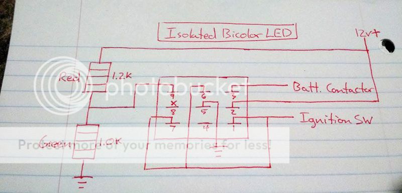
Someone drew this for me today,and this is the kind of or level of playing field assistance I need.
Would you look at it and see if you agree?
Posted By: oldspark
Date Posted: October 25, 2014 at 2:25 AM
No, that'll blow the switch. You are shorting IGN+12V to GND via 5 & 6.
And the LEDs are not wires as I described.
And the LEDs are not wires as I described.
Posted By: 2therock
Date Posted: October 25, 2014 at 9:38 AM
Thank You,
I didn't like it when I seen it but that's the kind of diagram I need.
Your help has been great but it is too deeply described for me.
I didn't like it when I seen it but that's the kind of diagram I need.
Your help has been great but it is too deeply described for me.
Posted By: oldspark
Date Posted: October 25, 2014 at 7:59 PM
Howz about this....

Posted By: 2therock
Date Posted: October 26, 2014 at 12:12 AM
Now Your Talking!
Question:
On one pole (position 3) I'm going to have a constant 12v source from the AUX battery for position 3 so I can manually close the contactor with key on or off if the need arises.
The other pole (position one) is going to have an ignition on source.
I see 12v going to through the resistors to ground. I take it its OK to have this 12v source to be ignition on only to avoid the little parasitic drain when the key is off?
Starting to feel better about this again.
Posted By: 2therock
Date Posted: October 26, 2014 at 2:11 AM
Sigh.........!
Well, I cannot seem to be able to find that M2122 configured with the correct contacts and terminals available to order.
The closest I can find is a 2123. And its synchronous and may not require resistors? Its p/n M2123LCFW02.
Heh, I led us into that one. Sorry.
Here is drawing in the sand for it.
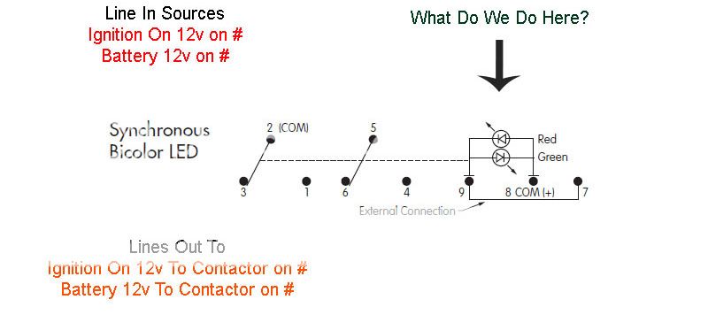
Well, I cannot seem to be able to find that M2122 configured with the correct contacts and terminals available to order.
The closest I can find is a 2123. And its synchronous and may not require resistors? Its p/n M2123LCFW02.
Heh, I led us into that one. Sorry.
Here is drawing in the sand for it.
Posted By: oldspark
Date Posted: October 26, 2014 at 3:25 AM
WHAT? You mean not only did you get me to draw a diagram (which I no longer do) and get me to update it (ha!), but now you're saying it was wasted? Lucky I had some coffee in front of me & most in me!
FWIW, the updated diagram BEFORE your last reply is below...
If the load is more than 1A (or say >~750mA) you might want to use a relay (with a 1N4004 or 1N4007 spike quenching diodes across its #3 connected coil) but then rethink the diodes.
IMO the 2123 description is vague. The wiring schematic as shown suggests no difference to the 2122 (just snip else ignore the #7 to #9 link); a 3PDT switch would suggest #7 shorted to #9 (ie, LEDs shorted) in shown #1 to #3 & #5 to #6 position, & #7 to #8 in the opposite position; and centre position is presumably all open as confirmed by the "OFF OPEN" centre position description.
But going by the description and how IMO it should operate (ie, NOT shorting across bi-color LEDs) it's the same wiring as for the M2122 except that BOTH LEDs will be off in the centre position.
Note that the illuminated LEDs in my original drawing will be RED in position shown (+12V powering the load); GREEN when centered (assuming the LOAD grounds the LED, else GREEN off or dim); and RED in the opposite position when IGN +12V is +12V (else all off).
Of course, please check my sanity... (That IMO is easier with my type of circuit diagram.)