adding additional accessory to door locking
Printed From: the12volt.com
Forum Name: Relays
Forum Discription: Relay Diagrams, SPDT Relays, SPST Relays, DPDT Relays, Latching Relays, etc.
URL: https://www.the12volt.com/installbay/forum_posts.asp?tid=138477
Printed Date: April 27, 2024 at 2:23 PM
Topic: adding additional accessory to door locking
Posted By: bach939
Subject: adding additional accessory to door locking
Date Posted: February 12, 2015 at 11:54 AM
This is somewhat a far fetched info request, but maybe someone can help me. I have a motorhome with a remote door lock system. I'm installing a motorized shutoff/turn on water valve. It normally the valve is activated by an on/on switch reversing the polarity to the valve. The motorized valve will automatically turn itself off when the valve reaches the end point, either in the on or off position. What I would really like to do is incorporate the valve into the remote door lock system so when I leave the coach and lock the door it will turn off the water valve and open it when I unlock the door. I need to know how I can do this knowing the valve needs a continued 12 volt to close and a continued 12 volts to open. I assume I will need relays to be connected to the door lock trigger wires to accomplish this, but my brain isn't capable to figure this out so, maybe some one here can help.
Replies:
Posted By: oldspark
Date Posted: February 12, 2015 at 4:22 PM
Are you sure it needs power to close? Usually solenoids (valves) only need power to actuate - eg, turn on - otherwise they drain batteries or open during power failures.
Posted By: bach939
Date Posted: February 13, 2015 at 12:11 PM
I understand what you are saying however, this valve is "motorized" meaning it turns the valve one way and/or the other. For an example, applying 12v positive will turn the ball valve closed. Applying negative or reversing polarity will turn the ball valve open. The valve has an internal limit switch turning off the input voltage therefore no more voltage will be used. The same when activated in reverse. So a on/on switch would work if I decide to use the switch because the internal limit switch will tu
Posted By: oldspark
Date Posted: February 13, 2015 at 2:54 PM
Cool. That solves continued power drain issues (and closing springs failing LOL).
I feel I'm stating the obvious, but IMO a timed circuit triggered by the lock command/action that triggers the valve close. Maybe a DEI 528T?
Timing may not be needed because of the limit switches tho I'd consider it a requirement to prevent the motor staying on in case of limit switch failure. Otherwise NC (normally closed) contacts when the home is locked but since that's probably not available it again brings me to a timer (since locks are short duration signals - ie +12V/GND or GND/+12V across a solenoid to lock & unlock).
If there is some lock status signal - eg a contact that indicates the door/doors is/are locked - then that could be used.
Another concern without a timed circuit is the constant drain of a relay (probably ~60mA or more) tho timer circuits using 555 timers (like the DEI-528T) themselves use 10mA in standby mode.
Then again, a MOSFET could be used instead of a relay (how electronically DIY are you?) or maybe the closed limit switch could be used to power the timer or in conjunction with the lock signal.
It mostly depends on what circuits exist - ie, signals, power outputs, and their polarities.
Are their circuit diagrams (schematics) available?
Posted By: howie ll
Date Posted: February 14, 2015 at 6:15 AM
Go with a 528t
-------------
Amateurs assume, don't test and have problems; pros test first. I am not a free install service.
Read the installation manual, do a search here or online for your vehicle wiring before posting.
Posted By: bach939
Date Posted: February 14, 2015 at 9:24 AM
I'm not a really good DIY, but given enough info, direction and maybe drawings. I can figure it out. I agree with your thinking regarding a timed relay just incase the valve limit switch failed. I do have schematics. I scanned them and can post the picture if I figure how to attach or post it.
Posted By: bach939
Date Posted: February 14, 2015 at 9:56 AM
bach939 wrote:
I'm not a really good DIY, but given enough info, direction and maybe drawings. I can figure it out. I agree with your thinking regarding a timed relay just incase the valve limit switch failed. I do have schematics. I scanned them and can post the picture if I figure how to attach or post it.

Posted By: davep.
Date Posted: February 14, 2015 at 11:03 PM
Here's my idea. Sorry for the crude sketch.
The flaw in this circuit is that 3 relays will be energized when the valve is ON, and the doors are unlocked. 450ma draw. About 10 Amp Hrs in 24 hours. You might consider a toggle switch in the power to the array to turn it off if you are dry-camping. If you are plugged-in at a park, no biggie. The draw won't hurt a thing. There is 0-draw when the array is turned off with a LOCK input. (The valve will also CLOSE). You could use the switch so the valve would stay in its current state (when the switch is turned OFF) regardless of what you do with the power locks.
Have fun...
```````````````````````````````````````
Description:
The bottom 2 relays receive pulses from the lock module.
When unlocked, the lower left relay latches on, and also turns on the upper relays. (Blue circuit in diagram)
The lower right relay when locked, releases the latch, and the relays all turn off.
The upper relays #30 are the output to the motor. The #87 N/O contacts are OPEN polarity when the array is latched ON. The #87a N/C contacts are CLOSE polarity to the motor, when the array is released.
There is a legend in the upper right that has the terminal numbers for the relays.
The text fields are too small. Here's the description of the functions of wire colors:
Red on left = + 12Volts, Hot at all times, or optional switch. See opening paragraph.
Black on left = Ground
Blue at bottom left = (+) Lock input. Brn/wht at lock module. Note the diode. Band towards relay.
Green at bottom right = (+) Unlock input. Pur/wht at lock module.
Green at Top = Output to motor wire that is (+) to CLOSE
Yellow at Top = Output to motor wire that is (+) to OPEN.
  [/IMG]
Posted By: oldspark
Date Posted: February 15, 2015 at 4:46 AM
Hey bach, looking at that diagram I agree with Howie - go with the DEI528T. The grounding lock pulse initiates the 528T output which energises the valve close signal/relay.
Separate/multiple lock inputs can be diode connected together to the 528T trigger (diode line-end towards lock GND signals - ie away from the 528T input).
Posted By: bach939
Date Posted: February 16, 2015 at 7:23 AM
davep. wrote:
Here's my idea. Sorry for the crude sketch.
The flaw in this circuit is that 3 relays will be energized when the valve is ON, and the doors are unlocked. 450ma draw. About 10 Amp Hrs in 24 hours. You might consider a toggle switch in the power to the array to turn it off if you are dry-camping. If you are plugged-in at a park, no biggie. The draw won't hurt a thing. There is 0-draw when the array is turned off with a LOCK input. (The valve will also CLOSE). You could use the switch so the valve would stay in its current state (when the switch is turned OFF) regardless of what you do with the power locks.
Have fun...
```````````````````````````````````````
Description:
The bottom 2 relays receive pulses from the lock module.
When unlocked, the lower left relay latches on, and also turns on the upper relays. (Blue circuit in diagram)
The lower right relay when locked, releases the latch, and the relays all turn off.
The upper relays #30 are the output to the motor. The #87 N/O contacts are OPEN polarity when the array is latched ON. The #87a N/C contacts are CLOSE polarity to the motor, when the array is released.
There is a legend in the upper right that has the terminal numbers for the relays.
The text fields are too small. Here's the description of the functions of wire colors:
Red on left = + 12Volts, Hot at all times, or optional switch. See opening paragraph.
Black on left = Ground
Blue at bottom left = (+) Lock input. Brn/wht at lock module. Note the diode. Band towards relay.
Green at bottom right = (+) Unlock input. Pur/wht at lock module.
Green at Top = Output to motor wire that is (+) to CLOSE
Yellow at Top = Output to motor wire that is (+) to OPEN.
[/IMG]
Hi Jim, I would start with the output wires used to lock and unlock the actuators. The Pro controller has 3 separate output legs, 2 wires each coming out of the 6 wire plug. Each pair has ground at rest and one wire out of the pair has about a 1/2 second of 12 volt positive when you lock and unlock the system. Start by testing these outputs with your ball valve to see if its possible. The other option is a more complicated relay. Thank you, Chad
Great info and instructions. And thanks for the drawing too!
Here is the info I got from the manufacturer of the door locking system regarding triggers wires. Don't know if you need it, but here it is if you do.
Hi Jim,
I would start with the output wires used to lock and unlock the actuators.
The Pro controller has 3 separate output legs, 2 wires each coming out of
the 6 wire plug. Each pair has ground at rest and one wire out of the pair
has about a 1/2 second of 12 volt positive when you lock and unlock the
system.
Start by testing these outputs with your ball valve to see if its possible.
The other option is a more complicated relay.
Thank you,
Chad
Posted By: bach939
Date Posted: February 16, 2015 at 12:00 PM
davep. wrote:
Here's my idea. Sorry for the crude sketch.
The flaw in this circuit is that 3 relays will be energized when the valve is ON, and the doors are unlocked. 450ma draw. About 10 Amp Hrs in 24 hours. You might consider a toggle switch in the power to the array to turn it off if you are dry-camping. If you are plugged-in at a park, no biggie. The draw won't hurt a thing. There is 0-draw when the array is turned off with a LOCK input. (The valve will also CLOSE). You could use the switch so the valve would stay in its current state (when the switch is turned OFF) regardless of what you do with the power locks.
Have fun...
```````````````````````````````````````
Description:
The bottom 2 relays receive pulses from the lock module.
When unlocked, the lower left relay latches on, and also turns on the upper relays. (Blue circuit in diagram)
The lower right relay when locked, releases the latch, and the relays all turn off.
The upper relays #30 are the output to the motor. The #87 N/O contacts are OPEN polarity when the array is latched ON. The #87a N/C contacts are CLOSE polarity to the motor, when the array is released.
There is a legend in the upper right that has the terminal numbers for the relays.
The text fields are too small. Here's the description of the functions of wire colors:
Red on left = + 12Volts, Hot at all times, or optional switch. See opening paragraph.
Black on left = Ground
Blue at bottom left = (+) Lock input. Brn/wht at lock module. Note the diode. Band towards relay.
Green at bottom right = (+) Unlock input. Pur/wht at lock module.
Green at Top = Output to motor wire that is (+) to CLOSE
Yellow at Top = Output to motor wire that is (+) to OPEN.
Are you suggesting to use DEI 528T as "old spark" states?
Posted By: oldspark
Date Posted: February 20, 2015 at 11:43 PM
Hey Jim, not that I'm one for interim responses... (LOL - I'm between wash cycles.)
But FYI my basic idea is something like the following as per REUK.co.uk's Automatic Hen House Door Closer Opener, namely:
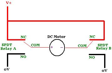
That's with a view to BOTH closing the valve upon exit/lock and reopening upon entry/unlock, and it's in principle only - I'll consider meshing with your two DEI 528Ts later.
The DEI528Ts might do it alone since they have SPDT relay outputs (I think...  ) - and your motor is well under 1A - but I'm looking at the 528Ts self powering off plus integration with your existing manual switch. (Maybe swapping the +12V to the relays' NO contacts and adding a few diodes...?)
The power-off may not be required but I'm assuming the 528Ts use a standard 555 timer and hence present a constant drain of 10mA (hence 20mA total) which tho ok for a vehicle that is run every few days may not be good for a motorhome etc that sits idle for lengthy periods. (Of course a master on-off switch could be fitted to disable the 528Ts when not required for lengthy periods.)
I did look at H-bridge circuits since your valve uses similar or less current than a typical automotive relay (was it 80mA?), but I considered them too impracticable for your application - ie, soldering; non-commercially readily available sparts; etc.
Anyhow, the washing has stopped and it's still 33°C (91°F) outside. Cool!
Posted By: bach939
Date Posted: February 28, 2015 at 6:00 PM
This subject us closed with success thanks for the help members!
|