I'm trying to cover the gaps in a blinker lead from the cluster in a p30 bread truck... to maintain a relay for side view cameras... is a 1000uF going to pull to much of a draw to charge or should I use something smaller? 470uF 220uF? I grabbed a couple from Radio shack... just not familiar with the smaller ones...
Basically I'm going to cross 85/86 with it 85 will be a lead from the turn signal indicator in the gauge cluster so it powers up when the turn signals are on... I realize there will be a slight delay in it shutting down also trying to shorten that delay time if I can...
Its "hold on" time is proportional to the cap size.
I've never liked that circuit. I prefer to use a transistor to buffer the (flasher) input thereby requiring a far smaller capacitor and less demand on (current from) the input.
Whereas a relay coil requires 60-250mA, a transistor requires nA for MOSFETs to mA for BJTs (aka normal(??) bipolar transistors) hence a hundreds to millions times smaller cap.
Oldspark, I've never used Resistors... so are you saying just run the input thru a resistor then to the cap/ relay and it will has a far smaller draw... or am I missing something? and what resistor would I rum?
I misspoke, I meant to put Transistors rather than resistors...
What I'm saying is to use a separate timed circuit - ie, a delay of (say) 1 second (aka pulse extenders etc) to stay on during the blinker off cycle.
These are commonly used for running light dimming etc (eg, see
exledusa.com's TPC Modules).
Tho some can use PICAXE 08 chips, many use 555 or other timer circuits or even "simple" RC circuits.
RC circuits are merely resistor & capacitor circuits where the capacitor is charged immediately and discharges thru a resistor (Google RC circuit. I used to recommend Wiki but several years ago they went from simple layfriendly explanations to heavy geek stuff.)
A diode is added to prevent the cap discharging back thru the source.
The delay (aka Time Constant) is proportional to RC, ie, R * C (Ohms, Farads. seconds).
That circuit that I never liked - namely relaydiagram22
Pulsed to Steady Output (Turn signal output to steady output for duration of turn signal) - is such an RC circuit where R is the relay coil resistance and hence say 48 Ohms to maybe 160 Ohms. (Ignore the 10k resistor - it has negligible timing effect compared to the relay coil.)
Because R is so small, C needs to be large for a given delay.
Hence the use off a
buffer like a transistor so that the RC applies to the transistor Base current (or FET's Gate current) and the transistor then turns on the higher current to the relay coil. (it
amplifies its Base (or Gate) signal.)
Apart from the smaller cap required, the RC buffer circuit can also overcome relay chatter that can occur with the cap & relay coil (because of the decay associated with RC circuits).
The
shut down delay will be whatever the
keep on (or "
hold off") delay is. That cannot be avoided. (Even the exledusa TPC modules exhibit that.)
The only way to overcome that is a rewire of your blinker circuit - namely where the flasher can is bypassed (removed & shorted) and the blinker (& hazard) switch switches relays for each side and those relays connect the blinkers to the flasher can.
The latter is the common OEM method used to control combined blinker/stop (or reverse) light systems whereby the relays also disconnect stop or reverse or running lights. But otherwise that involves OEM vehicle rewiring so many use the
add on time delay system instead. (The OEM implementation is usually part of the blinker switch as opposed to relays.)
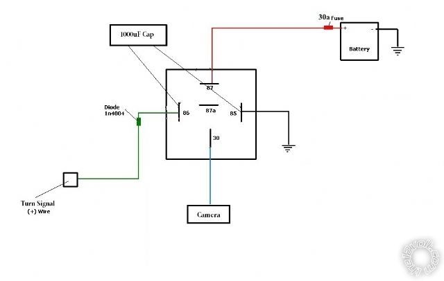
That's getting a bit over my head till I can do some more research and reading... my thought was just this... forgive the fuse I used an old diagram and didn't update the fuse size...
Yes - that's what I thought you stated and you were inquiring about using a smaller cap (which reduces the "on" time).
Your fig is the same as the12volt's
relaydiagram22 but omits the 10k resistor (I have often questioned its purpose...) and does not highlight the +ve end of the electrolytic cap.
If your question was simply about using smaller caps - sure, just connect them in parallel. If 470u or 220u has insufficient delay then add more. (Ah - the beauty of parallel additions - just
add across.)
The fuse is fine - your fig shows the
complete wiring - though the fuse can be MUCH smaller...
Speaking of which, depending on the voltage range of the camera, if the camera consumes less current than the relay coil, why use the relay at all? EG - if the camera requires say +8V or +10V to operate, use the diode and parallel cap to power it. It's only if the camera requires say +12V or +11V to operate that the relay would be used, ie the relay keeps +12V connected (meaning up to 14.5V etc) to the camera despite the cap voltage and hence output = relay coil voltage decaying to 8V or 4V etc (depending on the relay's
drop out voltage).
Anyhow, the fuse and wiring need only be sufficient to handle the camera current.
I doubt the camera would exceed 1A but I'd probably use a 5A or 10A (ATS style) fuse being the smallest commonly available & convenient automotive fuse with relay & wiring ratings above that (ie, the fuse must be rated to larger than the smallest downstream rating - eg a 15A or 30A relay and 10A wire means a 10A fuse or smaller).
Maybe a DEI 528T would suit? It's settable from about 1 sec to 45 secs tho I don't know if its output retriggers upon intervening input pulses.
It uses a 555 timer and - as I recall - a
missing pulse type function (which this is - ie, keep output on whilst it's retriggered withing a certain time period) does not use the 555's
conventional input (pin 2) as the input/trigger.
Otherwise the 528T could be hacked, or a 555 circuit built, or various equivalents. A 555 can power a load/camera of 200mA direct, else thru a transistor or relay etc.