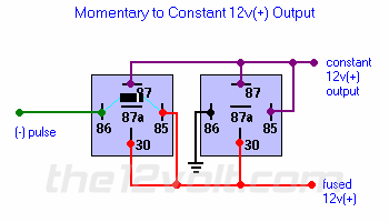
would it not be easier to set it up like this?
86 - 12v
85 - negative pulse
30 & 87- ground
and diode from 87 -> 85 with cathode facing 85
then change polarity after the fact.
this diagram makes my brain hurt.....i dont understand how it works, but i tested it and it does. If i had to improvise in a car this may go terribly wrong and the way i suggested is alot more idiot proof.
You would still need two relays if you need a constant 12V+ output with a momentary ground pulse. You would also need a diode on the lead you have going to 85 if connected to an alarm, keyless entry, etc. if you do not wish it to maintain a constant ground once activated. You would still want a diode across the coil of the relay and you would not need a diode between 87 and 85. The diagram above changes polarity first (left relay), then engages the latch (right relay). Typically when I use this configuration, the 12V+ supply is an ignition source that would cause the configuration to reset when the ignition source is turned off or interrupted. Ground could also be interrupted on the second relay to reset the configuration.
-------------
 the12volt • Support the12volt.com
 the12volt •