Three Pulses converted to one pulse
Printed From: the12volt.com
Forum Name: Relays
Forum Discription: Relay Diagrams, SPDT Relays, SPST Relays, DPDT Relays, Latching Relays, etc.
URL: https://www.the12volt.com/installbay/forum_posts.asp?tid=41434
Printed Date: May 28, 2024 at 11:33 PM
Topic: Three Pulses converted to one pulse
Posted By: neener
Subject: Three Pulses converted to one pulse
Date Posted: October 22, 2004 at 3:44 PM
I am having trouble wiring this up? I want to add a remote start to my factory keyless entry, but I want to be able to activate the remote start by pressing Lock -> Unlock -> Lock on the transmitter. What I need is to get one single negative output after pressing the buttons in the correct sequence to acitvate the remote start. Or if anyone has a better idea on how to do this, I am open to suggestions. I don't like the idea of having to just press the Lock button three times to start the car, because sometimes when I am trying to lock the doors I will keep pressing Lock til the horn honks that way I know the doors are locked. I am using a CrimeStopper RS-901 add on remote start. To start it will take either a single negative pulse or three negative pulses.
Replies:
Posted By: hotwaterwizard
Date Posted: October 22, 2004 at 8:26 PM
Do you have a Diagram of the output Relays? Or does it have a single wire? Does this have Outputs that Reverse Polarity on a solenoid. Help me out I am in the Dark here. Shed some Light on the way it is wired so I can Design you a circuit. This could get a bit complicated. Lock -> Unlock -> Lock ------------- John DeRosa (Hotwaterwizard)
Stockton California
When in doubt, try it out !
Posted By: hotwaterwizard
Date Posted: October 22, 2004 at 8:55 PM
Here is what I mean by complicated. | This circuit can be usefully employed in cars so that the car can start only when the correct code sequence is keyed in via the keypad. The circuit can also be used in various other applications. |

------------- John DeRosa (Hotwaterwizard)
Stockton California
When in doubt, try it out !
Posted By: BNLUIS
Date Posted: October 22, 2004 at 10:05 PM
Get an Audiovox (Prestige) stand alone Remote car starter. it utilizes the door lock motors to activate. Unlike most of the that need to be pulsed 3 times. The udiovox uses the motor lock and unlock motor +++++=======lock-unlock-lock ------------- Luis
Sound Waves
Is up to the installer to test all wires with a DMM whenever possible.
Posted By: neener
Date Posted: October 22, 2004 at 11:08 PM
Maybe I didn't explain myself good enough. What I want to do is pres Lock -> Unlock -> Lock -> on the transmitter, by using the power lock wires as triggers for the relays how can I wire up a relay(s) to either send a single pulse from this sequence or send three seperate pulses from this sequence to the negative remote start trigger. If I just wire up the lock and unlock wire to the (-) negative trigger of the remote start it would start on any three button press sequence. I hope this explains a little more what I want.
Posted By: hotwaterwizard
Date Posted: October 22, 2004 at 11:49 PM
With the Circuit I gave you you can not do that. So lets get a wiring diagram of what you have and design what you want together. ------------- John DeRosa (Hotwaterwizard)
Stockton California
When in doubt, try it out !
Posted By: go2pac
Date Posted: October 23, 2004 at 4:12 AM
The TR-7 will take 3 pulses within a programmed amount of time and give you one pulse. TR-7
Posted By: neener
Date Posted: October 23, 2004 at 11:26 AM
I dpn't have a wiring diagram yet, that is why I amasking for help here. If the lock and unlock wires are the triggers how would I wire up the relays?
Posted By: neener
Date Posted: October 23, 2004 at 12:27 PM
Will the TR-7 be able to give me a pulse using the lock and unlock pulses from the keyless entry. I looked at the documentation on pac-audio website and it looks like it only takes one trigger multiple times with a time limit to create on pulse out.
Posted By: hotwaterwizard
Date Posted: October 24, 2004 at 8:46 PM
Could you use 3 seperate buttons instead of 2? Then we could use a Decimal decoder.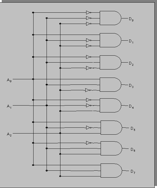 ------------- John DeRosa (Hotwaterwizard)
Stockton California
When in doubt, try it out !
Posted By: neener
Date Posted: October 24, 2004 at 10:01 PM
I would only have two triggers from the door locks (lock and unlock). I am using the factory keyless entry to trigger the relays.
Posted By: hotwaterwizard
Date Posted: October 24, 2004 at 10:23 PM
12v Negitive Pulse from each?
-------------
John DeRosa (Hotwaterwizard)
Stockton California
When in doubt, try it out !
Posted By: neener
Date Posted: October 25, 2004 at 8:38 AM
Yes a negative pulse from each.
Posted By: hotwaterwizard
Date Posted: October 25, 2004 at 6:17 PM
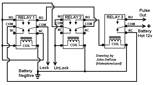
I am working on the Idea of using 3 relays. Latch the first Relay with the first pulse . The second Pulse will go thru the first relay and latch the second relay This will allow the third pulse to go thru the first and second relay and unlatch the whole mess. If the up Button is Pushed Multipul times nothing will happen, if the down is pushed Multiple Times Nothing will happen if up and down are pushed and down is pushed again nothing happens, if up then down then up are pushed it releases the third relay and sends a pulse out to the box.I am still working on it.
-------------
John DeRosa (Hotwaterwizard)
Stockton California
When in doubt, try it out !
Posted By: hotwaterwizard
Date Posted: October 26, 2004 at 12:37 AM
Here is what I came up with. It has not been tested!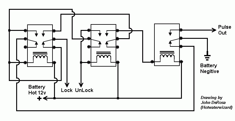 ------------- John DeRosa (Hotwaterwizard)
Stockton California
When in doubt, try it out !
Posted By: neener
Date Posted: October 26, 2004 at 12:36 PM
OK, I will try and wire this up and test it. I am assuming that the two relays on the left are DPDT, and order of contacts from top to bottom are NO-COM-NC. I have never worked with a DPDT relay before so please correct me if I am wrong.
Posted By: hotwaterwizard
Date Posted: October 26, 2004 at 4:55 PM
If you don't have DPDT you can use 2 Cube Relays in Tandum Just hook the coils together.
-------------
John DeRosa (Hotwaterwizard)
Stockton California
When in doubt, try it out !
Posted By: hotwaterwizard
Date Posted: October 26, 2004 at 7:33 PM
Here is the same circuit using Cube Relays. 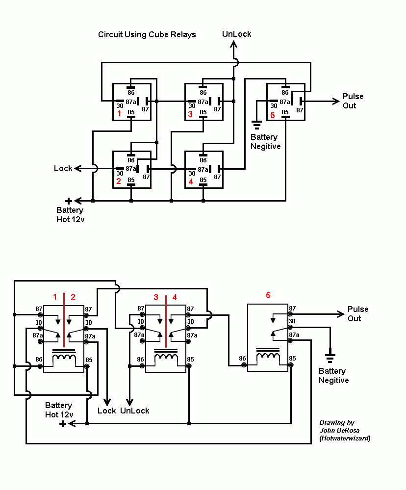
------------- John DeRosa (Hotwaterwizard)
Stockton California
When in doubt, try it out !
Posted By: neener
Date Posted: October 27, 2004 at 9:48 AM
I will pick up some relays this weekend and give it a try. John, Thanks for your help on this one.
Posted By: neener
Date Posted: October 28, 2004 at 2:14 PM
One more question. Without using a timer realy to control the 12 volt constant pressing Lock then half hour later Unlock and Lock it will trigger the remote start. The latched output is not timed so any amount of time between the triggers could trigger the remote start correct? So is it a good idea to use a timed relay triggererd by the Lock output to supply power to the relays for a set amount of time. This would ensure that the Lock->Unlock->Lock sequence would only work with a specified amount of time.
Posted By: hotwaterwizard
Date Posted: October 28, 2004 at 5:35 PM
This is true also it may need a Resistor and Capacitor to send the pulse Properly 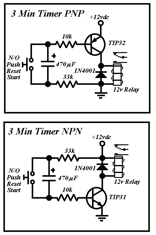 ------------- John DeRosa (Hotwaterwizard)
Stockton California
When in doubt, try it out !
Posted By: neener
Date Posted: October 30, 2004 at 9:51 PM
John, Need your help again. I wired up my relays, but when I pulse the Lock wire I get a buzz from relay #2. I wired them up using 2 DPDT relays and one SPDT. If I trigger the Unlock wire I will get relays 1,2,3 and 4 to latch, and they will unlatch when I trigger the Lock wire but I get the buzzing again. The is the first time I have worked with DPDT relays so just to make sure that I am wiring them up correctly this is what I have done. First of all I am using RadioShack model 275-218 if this helps any. Second It seems that on this relay the order of contacts from top to bottom are 87a - 87 - 30 - 86 ( assuming we are talking about relay #1 in your diagram). So I made the changes to my diagram so that the wires are in the correct place. Your help is greatly appreciated.
Posted By: neener
Date Posted: November 02, 2004 at 11:06 AM
My door lock triggers (Lock and Unlock) are positive triggers as opposed to previosly stating they were negative. How would I make this change?
Posted By: hotwaterwizard
Date Posted: November 02, 2004 at 4:55 PM
EASY Just switch the Positive with the Negitive
-------------
John DeRosa (Hotwaterwizard)
Stockton California
When in doubt, try it out !
Posted By: neener
Date Posted: November 03, 2004 at 10:44 AM
Any idea why the first relay(lock) won't latch when being triggered. The unlock will triggered and when I trigger the lock again it will unlatch the unlock.
Posted By: hotwaterwizard
Date Posted: November 03, 2004 at 6:58 PM
Recheck the wires make sure all of the jumpers are in place
-------------
John DeRosa (Hotwaterwizard)
Stockton California
When in doubt, try it out !
Posted By: hotwaterwizard
Date Posted: November 03, 2004 at 7:13 PM
Hook the Relays up one at a time testing as you go. I will Make it easy. You will need a Battery and a 12v light bulb.
-------------
John DeRosa (Hotwaterwizard)
Stockton California
When in doubt, try it out !
Posted By: ravenndude
Date Posted: November 04, 2004 at 3:27 PM
I really like this idea.
I was thinking of ripping out my my current aftermarket alarm (one a prevous owner had installed) and adding one with a remote start. But i like this idea a lot better!!!
What kind of remote start would you guys recomend? or can i just make one with relays since i have an automatic.
Posted By: hotwaterwizard
Date Posted: November 04, 2004 at 9:22 PM
Here is a Step by Step TEST that will test each section by it's self. This will confirm that each Section is working Properly. 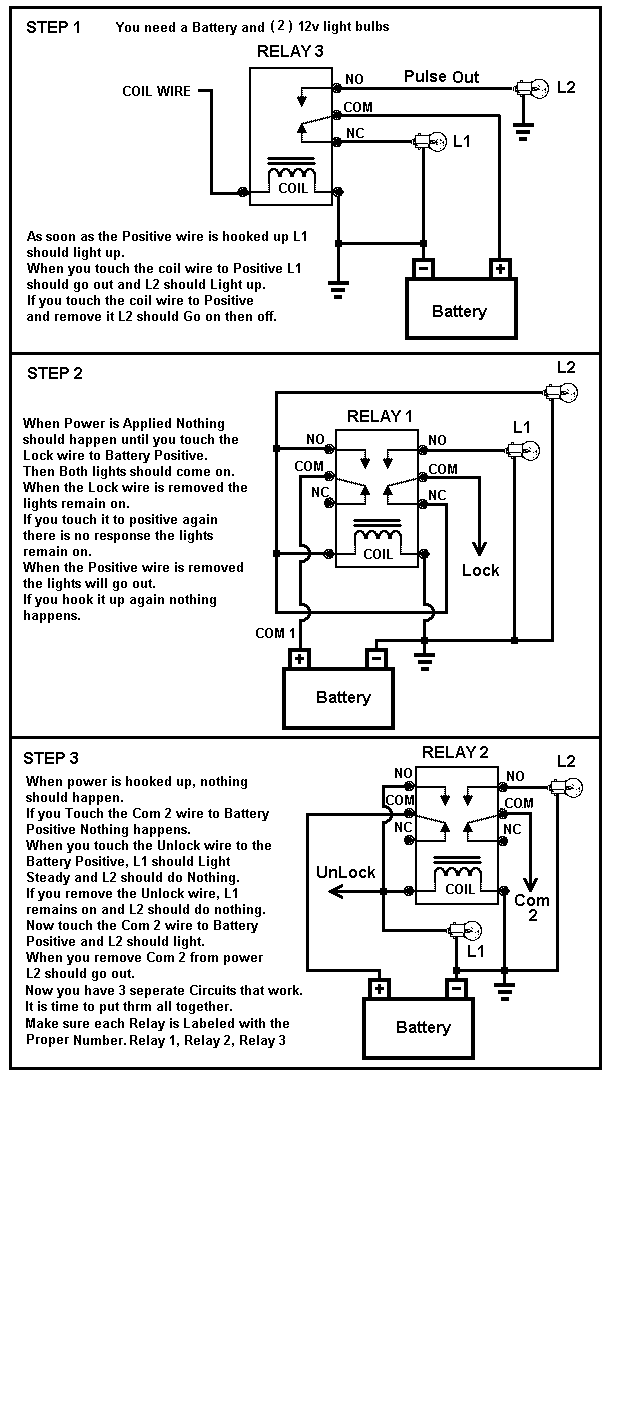
------------- John DeRosa (Hotwaterwizard)
Stockton California
When in doubt, try it out !
Posted By: go2pac
Date Posted: November 05, 2004 at 2:00 AM
Unfortunately the above diagram won't work correctly.
1. The pulse output will be too quick. The output should stay on as long as the doorlock pulse.
2. The first relay will latch again staying energized. We need to keep the circuit off after you complete the sequence.
3. Plus the circuit would give you a pulse if you started with unlock and then lock. Only two pulses are need to get a pulse output. You wanted 3 pulses.
The diagram below will work based off your lock, unlock then lock sequence. It is based off my Latched On/Off Output Using a Single Momentary Pulse diagram that the12volt decided to use without my permission. The original diagram is here.
The diagram below must be done by lock, unlock then lock sequence to work. If you try to do unlock then lock, no pulse. But since lock has now been triggered, then doing unlock then lock will give you a pulse output.
I forgot to draw the timer in, but what you need is a timer that takes a positive pulse that is triggered off of relay 3, terminal 87a and gives you a negative pulse output for lets say 10 seconds. Use the negative output to supply a ground to relay 2, terminal #86. If you need me to draw it in the diagram, let me know.
So hopefully when the12volt uses this diagram, they will give me credit instead of redrawing it and posting it like they designed it.

Questions for installers who know how to work with our TR-7: I'm designing a more advanced TR-7 (TR-8?, I have not decided what part #)with more trigger inputs. It may have 2 to 4 separate trigger inputs and maybe 4 to 6 outputs. It is going to be designed more for installer side than consumer because a programmer is going to be needed, which will use a laptop/desktop as the GUI. So what i like to know is what would you like to see in the TR-8? Is there something that is needed that the TR-7 did not cover? ------------- Karl
Pacific Accessory Corporation
Mobile Audio Interfacing Equipment
Connecting You to Your Music Since 1976
Posted By: hotwaterwizard
Date Posted: November 05, 2004 at 5:40 PM
He requires only one pulse. He wanted it to be a combination Lock too He wanted to push Lock then Unlock then lock again to get a single pulse out of Relay #3. The first Pulse will Latch Relay 1 and switch the Positive to Relay 2 and the second Pulse will Latch Relay 2 sending the positive to relay 3 the third pulse will unlatch Relays one and 2 and send the one pulse out to the output. I agree there should be a small delay but I haven't figured out how to do it the easy way yet. ------------- John DeRosa (Hotwaterwizard)
Stockton California
When in doubt, try it out !
Posted By: go2pac
Date Posted: November 05, 2004 at 6:45 PM
I understand what he wants. Its just your diagram won't work correctly. You can get a pulse from your diagram if you did unlock then lock without initially starting with lock. He specifically wants lock, unlock then lock to get a pulse. With my diagram you must start with lock, then unlock, then lock. Plus even if you get your pulse output (which will be very short, not long enough to trigger most remote starts) and unlatch all the relays, the pulse from the lock will latch relay 1 again.
-------------
Karl
Pacific Accessory Corporation
Mobile Audio Interfacing Equipment
Connecting You to Your Music Since 1976
Posted By: hotwaterwizard
Date Posted: November 05, 2004 at 7:21 PM
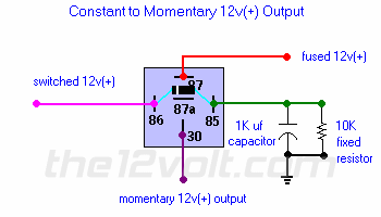
We culd somehow add this into the Mix. https://www.the12volt.com/relays/page5.asp#ctm Constant to Momentary Output
The capacitor allows the coil of the relay to be energized until the capacitor stores a charge, thus de-energizing the coil. The resistor bleeds off the charge of the capacitor when positive voltage is removed from the other side of the coil. You can increase the output time by simply changing the value of the capacitor. This one will give you about a 1/2 second output.
------------- John DeRosa (Hotwaterwizard)
Stockton California
When in doubt, try it out !
Posted By: fbird08
Date Posted: November 09, 2004 at 8:55 PM
This should work: PS: dont mind the extra random relay I just forgot to delet it 
------------- Money is just paper
Power is fleeting
But your word is everything,
If your word means nothing,
You are nothing...think about it
Posted By: fbird08
Date Posted: November 09, 2004 at 9:03 PM
how do you post something out of paint?? or is it just on my computer that my diagram comes up as a little red x??
-------------
Money is just paper
Power is fleeting
But your word is everything,
If your word means nothing,
You are nothing...think about it
Posted By: hotwaterwizard
Date Posted: November 09, 2004 at 9:17 PM
BMP is not Allowed. You have to change the Format to JPEG or GIF Then post it. If it is bigger than 30kb it won't go. If you have trouble Converting it just Email it to me and I will Convert it and send it back to you. hotwaterwizard@aol.com ------------- John DeRosa (Hotwaterwizard)
Stockton California
When in doubt, try it out !
Posted By: fbird08
Date Posted: November 09, 2004 at 10:26 PM
the last one was JPEG we'll try GIF this time  . Also just set the pulse relay timer for negative trigger and have it latch for a little longer than you think it will take you to hit the lock, unlock, then lock again. Again ignore the random relay . Also just set the pulse relay timer for negative trigger and have it latch for a little longer than you think it will take you to hit the lock, unlock, then lock again. Again ignore the random relay 
------------- Money is just paper
Power is fleeting
But your word is everything,
If your word means nothing,
You are nothing...think about it
Posted By: fbird08
Date Posted: November 09, 2004 at 10:27 PM
the last one was JPEG we'll try GIF this time  . Also just set the pulse relay timer for negative trigger and have it latch for a little longer than you think it will take you to hit the lock, unlock, then lock again. Again ignore the random relay . Also just set the pulse relay timer for negative trigger and have it latch for a little longer than you think it will take you to hit the lock, unlock, then lock again. Again ignore the random relay 
------------- Money is just paper
Power is fleeting
But your word is everything,
If your word means nothing,
You are nothing...think about it
Posted By: fbird08
Date Posted: November 09, 2004 at 10:29 PM
damn it!!! we'll see if hotwater wizard has better luck posting it
-------------
Money is just paper
Power is fleeting
But your word is everything,
If your word means nothing,
You are nothing...think about it
Posted By: hotwaterwizard
Date Posted: November 09, 2004 at 10:34 PM
TESTING 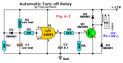 ------------- John DeRosa (Hotwaterwizard)
Stockton California
When in doubt, try it out !
Posted By: hotwaterwizard
Date Posted: November 09, 2004 at 10:40 PM
How's This? 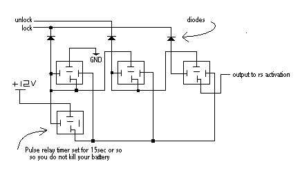 ------------- John DeRosa (Hotwaterwizard)
Stockton California
When in doubt, try it out !
Posted By: go2pac
Date Posted: November 11, 2004 at 5:21 PM
Looks good, but it needs to be positive lock and unlock instead of negative.
-------------
Karl
Pacific Accessory Corporation
Mobile Audio Interfacing Equipment
Connecting You to Your Music Since 1976
Posted By: fbird08
Date Posted: November 11, 2004 at 11:29 PM
Thanks for posting that for me hotwaterwizard. I was having one heck of a time getting that picture to load. As for the positive L/U I was under the assumpition that they were negative trigger but that is easily fixed. Just were it says 12V change that to ground, where it says ground change that to 12V, cut the loop on the pulse relay timer so it accepts a positive trigger and reverse the diodes. This will yield a positive output after a positive lock, unlock , then lock again. If a negative unlock is still needed all you have to do is add another relay onto the output to change the polarity. Just use the positive output to trigger the relay and have pin 87 hooked to ground and pin 30 will be your negative output. I've found that DEI 451Ms work great for little projects like this if you pay careful attention to what wire is what pin on the mini relays. They are easily confused simply because you cant vizually look at where the wire is hooked up. If you do end up using these there are two purple wires that are attached, the purple wire with the black stripe is hooked to the same relay as the white and green wires. BTW what kind of car is this? I didnt catch it in all the posts but I may have missed it. G-luck ------------- Money is just paper
Power is fleeting
But your word is everything,
If your word means nothing,
You are nothing...think about it
Posted By: fbird08
Date Posted: November 11, 2004 at 11:32 PM
Thanks for posting that for me hotwaterwizard. I was having one heck of a time getting that picture to load. As for the positive L/U I was under the assumpition that they were negative trigger but that is easily fixed. Just were it says 12V change that to ground, where it says ground change that to 12V, cut the loop on the pulse relay timer so it accepts a positive trigger and reverse the diodes. This will yield a positive output after a positive lock, unlock , then lock again. If a negative unlock is still needed all you have to do is add another relay onto the output to change the polarity. Just use the positive output to trigger the relay and have pin 87 hooked to ground and pin 30 will be your negative output. I've found that DEI 451Ms work great for little projects like this if you pay careful attention to what wire is what pin on the mini relays. They are easily confused simply because you cant vizually look at where the wire is hooked up. If you do end up using these there are two purple wires that are attached, the purple wire with the black stripe is hooked to the same relay as the white and green wires. BTW what kind of car is this? I didnt catch it in all the posts but I may have missed it. G-luck ------------- Money is just paper
Power is fleeting
But your word is everything,
If your word means nothing,
You are nothing...think about it
Posted By: neener
Date Posted: November 12, 2004 at 3:15 PM
Hey thanks everyone for all the help. The car is a 2003 Accord. I will give this a try when I get back home from a business trip.
Posted By: fbird08
Date Posted: November 12, 2004 at 10:00 PM
If it is a 2003 accord test the lock and unlock wires not the motor wires. I am pretty sure they will be negative pulse and my original diagram that hotwaterwizard posted for me will work with no modifications. The only concern is if the lock and unlock wires actually pulse when you use the remote. I know they do from the door switch and if you turn the key in the door key cylinder but I have never tried testing them when you use the factory key fob. Let us know how this turns out. ------------- Money is just paper
Power is fleeting
But your word is everything,
If your word means nothing,
You are nothing...think about it
Posted By: neener
Date Posted: November 16, 2004 at 11:22 AM
The lock and unlock wires do not pulse with the keyless entry remote.
|


 . Also just set the pulse relay timer for negative trigger and have it latch for a little longer than you think it will take you to hit the lock, unlock, then lock again. Again ignore the random relay
