speaker relay
Printed From: the12volt.com
Forum Name: Relays
Forum Discription: Relay Diagrams, SPDT Relays, SPST Relays, DPDT Relays, Latching Relays, etc.
URL: https://www.the12volt.com/installbay/forum_posts.asp?tid=66866
Printed Date: May 19, 2024 at 5:45 PM
Topic: speaker relay
Posted By: chrisp3
Subject: speaker relay
Date Posted: November 23, 2005 at 6:13 AM
HELP! This is a bit off the car audio topic...but I am trying to add a doorbell to an existing whole house audio system and need to know how to switch the speaker from the sudio system to the doorbell chimer when someone presses the button on the front door. I also need a soucre for a 24vdc relay. I am only switching one of the spkrs (out fo the pair) but need to do this on three differnet floors...(do I need three relays)? I don't know if I need...if if there is even such a thing..as a double pole or triple pole relay and need some guidance of how I might wire this up. If anyone can point me in the right direction I'd appreciate it. THANKS in advance
Replies:
Posted By: hotwaterwizard
Date Posted: November 24, 2005 at 2:07 PM
I need more details. Are there 3 different Door bell buttons. One button and 3 speakers hooked to the same output? One Button and 3 different outputs? Can the chime produce enough power for all 3 speakers? Does the Stereo system have a preamp input? A Schematic would help. ------------- John DeRosa (Hotwaterwizard)
Stockton California
When in doubt, try it out !
Posted By: chrisp3
Date Posted: November 25, 2005 at 12:46 PM
hotwaterwizard wrote:
I need more details. Are there 3 different Door bell buttons. No. There is only one button. One button and 3 speakers hooked to the same output? Yes. I am using a Valcom chime unit (model 9927A) with a simple contact closure setup. Each of the speakers is attached to a volume control thru a Niles Audio VCS HUB that has internal impedance matching capabilities (which essentially provides continuity to all of the speakers at all times and it somehow internally monitors the circuit to keep it from overloading the amp). Right now when the speakers are attached to the hub and I press the doorbell, nothing happens unless the volume control for that speaker is turned up. There is no way I can find to bypass the hub unless i physically remove the leads from the speaker and attach them to the Valcom unit. What I want to do is remove the speaker leads from the Niles HUB and insert a relay that is normally closed (thus allowing music to flow through it). When the button at the front door is depressed I want the relay to open (which will remove it from the Niles HUB) and momemtarily re-route it to the Valcom unit. Ultimatley I want the doorbell to take priorty over the speaker so that it will chime regardless of whether the volume control is turned on, off, or even if there is music passing through it.. One Button and 3 different outputs? One one button but three separate speakers (one on each floor). These speakers are normally playing music or mght be "at rest" with the volume control turned off. Can the chime produce enough power for all 3 speakers? Yes. Does the Stereo system have a preamp input? Yes it does but in order for it to work with a direct input to the amp....each volume control would always have to be "turned on" which might not always be the case. A Schematic would help. I am not good with drawing schematics although I can read them most of the time. Here is a block drawing which might give you enough info. If not...let me know what else I can provide. Thanks in advance for your time. Chris 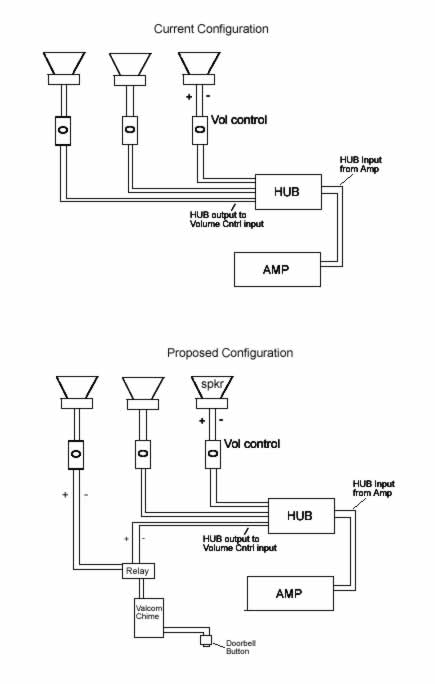
Posted By: KPierson
Date Posted: November 25, 2005 at 5:54 PM
There is such a thing as a 4PDT relay, four separate sets of contacts controlled by one coil. You should have no problem sourcing a 24VDC coil. Check out www.Digikey.com. You should be able to find an 'ice cube' relay, a small squarish relay that is made in a standard package, that you can buy relay bases for. ------------- Kevin Pierson
Posted By: hotwaterwizard
Date Posted: November 25, 2005 at 7:22 PM
If you could find where the music goes into the amp you could simply switch between the door bell and the music with a relay. Mono or Stereo? ------------- John DeRosa (Hotwaterwizard)
Stockton California
When in doubt, try it out !
Posted By: hotwaterwizard
Date Posted: November 25, 2005 at 8:06 PM
You can get the relay at any place that sells parts for HVAC controls. I get them at Johnstone Supply Appliance parts stores may have one as well. ------------- John DeRosa (Hotwaterwizard)
Stockton California
When in doubt, try it out !
Posted By: chrisp3
Date Posted: December 01, 2005 at 4:48 PM
Got it all hooked up today and all is good now. Speakers operate with music all the time. When the doorbell is pressed the relay switches the leads to the chime.....when the relay closes again...the music comes back on. You guy's are great! Thanks for the help. Now if I could only figure out what it will take to keep the relay open for 2-3 seconds. If I release the button too soon the chimer stops (because the relay is a m.o. and closes as soon as it loses power). It would be nice if I could press the button and have it remain in the open postion for a bit loger. Anyone know of a quick--inexpensive fix for this?
Posted By: hotwaterwizard
Date Posted: December 01, 2005 at 9:04 PM
This is a delayed on circuit you will have 5 seconds after power is supplied before the power comes on to the relay. If we could reverse the circuit some how. Hmmm Ummm I'll see what else I can come up with. ------------- John DeRosa (Hotwaterwizard)
Stockton California
When in doubt, try it out !
Posted By: KPierson
Date Posted: December 02, 2005 at 6:34 AM
What kind of time frame are you on for a 'cheap' fix? I have some circuit boards scheduled for delivery in the next week that might be able to help you out. They will have a fully adjustable delay that can be set up to do several different things. Let me know if you are interested in 'testing' one for me.
-------------
Kevin Pierson
Posted By: chrisp3
Date Posted: December 02, 2005 at 1:28 PM
My timeframe is sometime in the next couple of weeks. The installation is complete and the chime is working but there are some odds and ends that need to be cleaned up and we are waiting on parts. I would gladly accept your offer for testing. Thanks Chris
Posted By: KPierson
Date Posted: December 02, 2005 at 3:16 PM
Are you switching the positive or negative with the door bell switch? I was thinking of a setup like this: Pushing the button will pull the relay in The relay will stay pulled in for as long as the button is pushed Releasing the button will start the adjustable timer (0-30s roughly) Does that sound about right? ------------- Kevin Pierson
Posted By: hotwaterwizard
Date Posted: December 02, 2005 at 10:48 PM
AC Voltage works different than DC Voltage. We are dealing with 24vac. No Positive or Negitive. ------------- John DeRosa (Hotwaterwizard)
Stockton California
When in doubt, try it out !
Posted By: hotwaterwizard
Date Posted: December 02, 2005 at 11:03 PM
You could get a time delay relay relay from grainger with a 24v control voltage. https://www.grainger.com/Grainger/wwg/viewCatalogPDF.shtml?browserCompatable=true&adobeCompatable=true&toolbar=false&CatPage=410 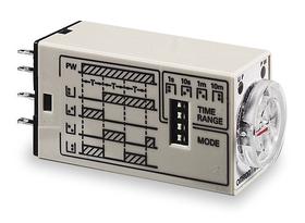
------------- John DeRosa (Hotwaterwizard)
Stockton California
When in doubt, try it out !
Posted By: KPierson
Date Posted: December 03, 2005 at 9:16 AM
Yeah I guess a transformer with no rectifier kind of gives that away, I'm not sure what I was thinking. Thats brings up a different question, the OP asked for a 24VDC relay in the first post, so what kind of relay are we using? My circuit should work with AC voltage, as long as its below 30v. I'll just have to software filter the AC signal to a DC signal. Outputing a signal to the relay may be a bit more tricky, but shouldn't be an issue, I'll have to go out in the garage and see if I can dig up a transformer and do some testing. All the componenets showed up yesterday, but the circuit boards won't be here till next Wednesday. ------------- Kevin Pierson
Posted By: chrisp3
Date Posted: December 03, 2005 at 1:00 PM
hotwaterwizard and KPierson-- You guy's are great and it looks like this topic has taken on a life of its own. Thanks for all the great information. Just to clarify the issue of voltage (AC vs DC), I am using 24Vdc. THe chiming unit uses -24Vdc and I ended up using 4PDT relays to break the speaker cirucits just after it leaves the volume control (as opposed to just after it leaves the hub as depicted in my earlier drawings). THis alows everything to work in a normal music environment and the relay only takes over when the doorbell button is depressed. As soon as it is released the relay closes and music starts back up. Installing the relay this way takes the volume control out of play when the doorbell rings thus allowing the chime to go directly to the speaker terminal without having to worry about whether that particular volume control is turned up. The only remaining thing I have to figure out is how to keep the relay activated long enough for the preprogrammed chime to play (roughly 3 seconds) and then where to insert this timer. I have looking at the DEI-528T but have never used one of these and don't know if it will sove my problem. THe current relays are already "wired in" and all of the cables are dressed....so I really hope I don't have to install a new set of relays. I would prefer to insert a timer in the button circuit as it is much easier than having to undress and rewire the entire panel. Thanks again fo all your assistance.
Posted By: KPierson
Date Posted: December 09, 2005 at 1:57 PM
Chris, The board should be here today! Where are you getting your 24VDC? Do you have a power supply providing it? We will need a 7-30vdc power source to power the microcontroller. The module will hook up to power, ground, door bell switch signal (which I will need to know if its a (+) or (-) signal, and the output will hook to the relay coil. Should be a simple install, no need to rewire the relay contacts at all. Thanks, ------------- Kevin Pierson
Posted By: chrisp3
Date Posted: December 09, 2005 at 3:17 PM
Hi Kevin, The chime unit is using -24Vdc. I am suppling this power via a 24Vdc 500ma transformer that simply plugs into the wall. It has screw terminals on the power supply so I hard wired it directly to the Valcom Chimer. I have access to either voltage (+ or -). I also have an additional power supply so if need be, I can use it to power your circuit. Let me know what questions I can answer......Thanks Chris
Posted By: KPierson
Date Posted: December 09, 2005 at 4:14 PM
The existing transformer should work fine, the module will only pull roughly 25mA. How is the coil of the relay hooked up now? Are you switching the (-) feed to the coil, or the (+)? With my module, we will have a switched (-) out capable of 100mA. So, technically, we would need the (-) side of the coil switched. This way, you could remove the (-) feed to the relay, input it in to my board, and then connect the output of my board to the (-) side of the coil. How does that sound? Oh, and I have one of the boards in my hand right now! All I have to do is write about 100 lines of code or so, and we'll be in business! ------------- Kevin Pierson
Posted By: chrisp3
Date Posted: December 09, 2005 at 4:24 PM
Sounds good. I believe that I am running -24 to the coil of the relay wheneve the button is pressed. As soon as the button is released....the coil de-energizes and go to N.O. Chris PS I am about to go out for the night (wife's xmas party) so I won't be able to respond to questions until tomorrow am.
Posted By: KPierson
Date Posted: December 11, 2005 at 12:27 PM
Got the module built and programmed last night. The module works just as I had described above. 4 wires:
Red - 7-35VDC input
Black - Ground
Green - 100mA (-) output
Orange - (-) input When you apply a (-) input to the orange wire the (-) output is turned on. The (-) output stays on until the input is removed. Once the input is removed the (-) output will stay on for a period of time proportial to how far the know is adjusted. The delayed output is adjustable from 0-30 seconds in 1/1024 increments (10bit resolution). The first pic is of the circuit itself. You can see the adjustment knob in the top right corner of the board. The IC chip operates at 1mhz, and draws roughly 8mA at idle. When the output is on the current draw will be roughly equivalent to the current draw of the relay coil itself + 10mA. The bottom picture is the module in its final state. Unfortunately for you, this was the first enclosure that we drilled a hole in, and its kinda sloppy, but I don't think you'll mind :) Please send me your shipping info (including full name) via PM and I'll drop in in the mail tomorrow or Tuesday. Thanks! 

------------- Kevin Pierson
Posted By: KPierson
Date Posted: December 11, 2005 at 4:13 PM
I had too much time on my hands during the Bengals/Browns game so I drew this up in AutoCAD: Does this look doable? 
------------- Kevin Pierson
Posted By: chrisp3
Date Posted: December 11, 2005 at 7:22 PM
IT looks doable...but I might suggest that we invert the 24Vdc signal from +24V to -24V. When I get the actual ckt I will play with it to see which voltage will actually work. I sent you a PM earlier.....let me know if you did not get it. Thanks
|