Momentary output with maintained input
Printed From: the12volt.com
Forum Name: Relays
Forum Discription: Relay Diagrams, SPDT Relays, SPST Relays, DPDT Relays, Latching Relays, etc.
URL: https://www.the12volt.com/installbay/forum_posts.asp?tid=70547
Printed Date: March 03, 2026 at 4:18 PM
Topic: Momentary output with maintained input
Posted By: djreiswig
Subject: Momentary output with maintained input
Date Posted: January 11, 2006 at 3:15 PM
I need a circuit that will take a maintained ground input and provide a momentary (less than one second) ground output. It would need to reset and provide the output once the ground input goes away and comes back again. This will be used to disarm a factory alarm system without unlocking the doors. That is why it needs to be a short pulse.
Replies:
Posted By: KPierson
Date Posted: January 11, 2006 at 5:49 PM
Are you looking for a circuit to build yourself or a commercially availible product?
-------------
Kevin Pierson
Posted By: djreiswig
Date Posted: January 11, 2006 at 6:13 PM
Would like to build myself if possible/practical.
Posted By: KPierson
Date Posted: January 11, 2006 at 7:18 PM
A pulse timer should work for this without a problem, there are several ways to build pulse timers. ------------- Kevin Pierson
Posted By: djreiswig
Date Posted: January 11, 2006 at 11:20 PM
What would be the best way with common components? Would the time be adjustable with a resistor or something?
Posted By: KPierson
Date Posted: January 12, 2006 at 6:37 AM
Should be able to do it with a 555timer and an RC circuit. For the R you can use an adjustable potentiometer to adjust the time of the pulse
-------------
Kevin Pierson
Posted By: djreiswig
Date Posted: January 12, 2006 at 6:53 AM
Could you come up with a circuit for me? I can build it, but I don't know how to design it. I don't do much electronic stuff.
Posted By: KPierson
Date Posted: January 12, 2006 at 2:02 PM
https://home.cogeco.ca/~rpaisley4/LM555Basics.GIF Taken from: https://home.cogeco.ca/~rpaisley4/LM555.html You would want the last circuit shown, a one second one shot. You want me to come install it for you, too? :) ------------- Kevin Pierson
Posted By: KPierson
Date Posted: January 12, 2006 at 2:03 PM
I didn't think ti would show up, the file neds in .GIF, and I've never gotten an uppercase extension to work on this site... 
------------- Kevin Pierson
Posted By: the12volt
Date Posted: January 12, 2006 at 2:09 PM
KPierson, the file extention was missing in your first post. -------------  the12volt Support the12volt.com the12volt Support the12volt.com
Posted By: KPierson
Date Posted: January 12, 2006 at 2:11 PM
Oh, and you will need to add a transistor to the output of pin 3 above. I would go with a 2n3904. Connect a 220 ohm resistor between pin 3 above, and the base of the transistor. Connect the emitter of the transistor directly to ground, connect one side of a diode to the collector, and connect the other side to 12vdc. Make sure the stripe of the diode is on the 12vdc side. Then, hook your relay in parallel with the diode (postivie to positive, negative to the collector side of the diode). It may be a good idea to put a resistor in series with the diode to limit the current otuput of the transistor, but the resistance of your relay coil should be enough to keep things happy. ------------- Kevin Pierson
Posted By: KPierson
Date Posted: January 12, 2006 at 3:27 PM
the12volt wrote:
KPierson, the file extention was missing in your first post.
Whenever I try to link to a file with all caps extension (i.ei picture.GIF) the extension is deleted after I hit the post button. The image shows up in the preview box, but disapears as soon as I hit post. I've even tried to go back in and edit the post, and add the .GIF again but it just got deleted again. ------------- Kevin Pierson
Posted By: djreiswig
Date Posted: January 12, 2006 at 4:03 PM
I think I am confused. I understand how to build the circuit, but where would I hook a maintained negative from my remote starter, and where would I get the momentary negative signal from?
Posted By: KPierson
Date Posted: January 12, 2006 at 5:23 PM
You maintained (-) would go to the input, where the switch is drawn (Pin 2, I believe, it would replace the switch). Your output is on pin 3. It will be a low current output, capable of around 25mA of current. You will need a transistor to amplify the current.
-------------
Kevin Pierson
Posted By: djreiswig
Date Posted: January 13, 2006 at 7:01 AM
So I hook 12V + to the top left marked +, my maintained negative goes to the top side of where the switch is shown (and take the switch out), (or does it go to the lower left where the O is?) And my momentary negative is off of the upper right where the O is. What goes to the lower right O? I am just grounding a door unlock signal wire to the BCM. Do you think this would be more than 25mA? How would the transistor hook up, if I would need one? Also, I see the formula on the schematic to change the pulse time. What would I use to get a shorter than 1 sec pulse? Say 1/2 sec or less.
Posted By: KPierson
Date Posted: January 14, 2006 at 3:24 AM
Yes, the 12vdc will go where the (+) is marked. I'm not 100% positive that a 555timer will operate above 12vdc, so you may want to look in to that (there should be a max voltage rating for the chip when you buy it). The (-) out of your alarm would go to the top side of where the switch would go, if you were using one, which you are not. The lower right O is the ground plane. You can't have a circuit without a + and a -. I would use a transistor on the output, hook it up like I stated above (220 ohm resistor between the output of the 555 timer and the base of the 2n3904 transistor. Tie the emitter to ground, and then if you just want a (-) output to drive a BCM I would hook a 47 ohm resistor to the collector of the transistor and the other side of the resistor will be a 100mA (-) output. Ha, the forumla is listed right on the sheet, I'm sure you have a calculator handy, just plug in the numbers. Pulse Time = 1.1 x R x C .5=1.1xRxC = .5=1.1 x 100,000 x C C = 4uF. Typically, you pick an availible capacitance and find the corresponding resistance. There are no set values for either component, you'll just have to make sure that both values are availible. ------------- Kevin Pierson
Posted By: djreiswig
Date Posted: January 19, 2006 at 7:57 AM
Is this correct? It should give me a .5 sec momentary negative. 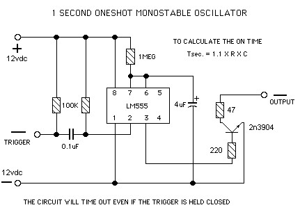
Posted By: djreiswig
Date Posted: January 27, 2006 at 6:55 AM
What happened to KPierson? I sent him a PM about this, and he hasn't been back here. Does anybody know if I have this right?
Posted By: KPierson
Date Posted: January 27, 2006 at 3:36 PM
Sorry, I've been in Ft. Lauderdale for the past two weeks. From my calculation your pulse would be 4.4 seconds (1.1 x 1000000 x 0.000004) = 4.4 I would try a resistor closer to 110Kohms. This should give you a 0.484 second pulse. ------------- Kevin Pierson
Posted By: djreiswig
Date Posted: January 27, 2006 at 6:36 PM
No problem. I don't come here often unless I have a question. So the resistor that goes to pin 7 on the timer is the one I change to make the pulse different? I guess that makes sense because that is the one with the formula by it (duh!) Does it look like it will work if I change the 1meg to 110K? I have the transistor and resistors like you described them?
Posted By: KPierson
Date Posted: January 27, 2006 at 6:47 PM
Yeah, everything else looks good, should work (with the 110K resistor). You're looking at about $4 in parts, so if it doesn't work at least you arn't out much.
-------------
Kevin Pierson
|