Would you use a diode in this situation?
Printed From: the12volt.com
Forum Name: Relays
Forum Discription: Relay Diagrams, SPDT Relays, SPST Relays, DPDT Relays, Latching Relays, etc.
URL: https://www.the12volt.com/installbay/forum_posts.asp?tid=7099
Printed Date: March 27, 2026 at 3:27 AM
Topic: Would you use a diode in this situation?
Posted By: Lee280zx
Subject: Would you use a diode in this situation?
Date Posted: December 24, 2002 at 12:15 PM
The moderator of this board has given me the following diagram which I will modify to interrupt my stock fuel pump relay wire (instead of the starter). I have repeatedly read the "Basics" section on diodes, but I just can't grasp what they accomplish when used with relays. Would you use diodes with this setup? What, in the most basic terms, do I risk if I don't use them? 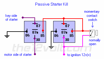
Replies:
Posted By: the12volt
Date Posted: December 24, 2002 at 1:31 PM
Lee I answered your question regarding the use of a diode across the coil of a relay in your original post here: You can also find an explanation for the use of diodes here which says " The diode provides a path for current when the current path to the relay is interrupted (i.e. switched off). This allows the coil field to collapse without the voltage spike that would otherwise be generated. The diode protects switch or relay contacts and other circuits that may be sensitive to voltage spikes." Is it necessary to use diodes across the coils of the relays shown above? No. But as I said before, it's a good idea to use them. The only thing you risk by not using them is shortening the life span of each relay.
Posted By: auex
Date Posted: December 24, 2002 at 1:47 PM
Personally I don't like doing ignition kill ( or fuel pump kill ). Contrary to belief relays do go bad. What would you do if the relay went out when you are driving? The engine would stall and you would be stuck ( especially if the relay is not accesible ). ------------- Certified Security Specialist
Always check info with a digital multimeter.
I promise to be good.
Tell Darwin I sent you.
I've been sick lately, sorry I won't be on much.
Posted By: the12volt
Date Posted: December 24, 2002 at 2:10 PM
Agreed, relays do fail, but not often enough to ever worry about them failing, unless of course you're using them in a situation that matches or exceeds their maximum current capacity.
Posted By: Lee280zx
Date Posted: December 24, 2002 at 4:05 PM
So, I would risk shortening the life of each relay if I don't use diodes. I know you referred me to that information before, but I just have to say that I still don't understand it--why the spike occurs and what it can do. If it is a low draw wire I'm interrupting (a signal wire), what is the big risk? Is the voltage spike more of a concern when the relay in question is being used to switch on and off high-amp device, like headlights or stereo amps? And I can't quite picture the method of installing the diode you suggested. It sounds like complicated, precise work. Because I am using relays actually made by Bosch, I presume they are of better quality and less likely to fail than some other brands. As far as the issue of potential failure, I'll carry a couple of extra relays in my car, and rig everything so I can easily bypass the relays if I need to. I appreciate all the advice. This is all new to me, and I have difficulty grasping all of it.
Posted By: TomEllis
Date Posted: December 27, 2002 at 3:14 PM
Lets see if I can explain this and not confuse you or me any more. The coil of the relay is an inductor, just like one half of a transformer. when you put voltage across the coil, it creates a magnetic field and energizes the relay. Now comes the bad part, when you remove the voltage the magnetic field collapses. This collapse creates a voltage spike, which has to go somewhere. This spike could go to the other relay in the circuit above, either one, and burn out the other coil or it could burn out it's own coil. This is the reason that you put a diode across the coil of the diode, especially in the circuit that you have shown above. The diode will take the voltage spike through itself, this gives the spike a path other than the coil. The amount of current through the contacts of the relay do not have any affect as to the amount of the voltage spike, it is determined by the inductance of the coil in the relay. It also does not matter how good quality the manufactor is unless they put diodes inside the relay across the coil. I hope this explanation has not confused you more, please let me know if you need more information. Tom
Posted By: Lee280zx
Date Posted: December 27, 2002 at 6:45 PM
Thanks, Tom, that explains it better. From what you say, the above setup is more likely to suffer such a problem than a setup involving a single relay. You recommend that I use diodes in this particular setup? (Some people have told me this spike is a very rare problem (in general--not as to this specific setup), and it seems like installing a diode will be a hassle, so I had thought I wouldn't use one. I couldn't find relays with internal or built-in diodes, and it sounded to me like this wasn't too much of a risk.) Thanks to everyone who has responded. My cognitive abilities are a bit impaired recently, so I've just had a hard time figuring this out to my satisfaction.
Posted By: TomEllis
Date Posted: December 30, 2002 at 1:10 PM
Lee280zx, 9 times out of 10 you will not have a problem. I personally like to put the diodes in for security. However, what people are telling you is correct, the spike is a rare problem and not putting a diode on will not put your system at a risk. In the dual relay setup that you showed above, if one relay should create a spike, that spike would go into the coil of the other relay and the + wiring. What it would do to the other relay is a question that I could not answer. There are other varibles that need to be answered to figure out what it would do the the wiring and relays. You are not wiring this setup to any electronics that are sensitive to voltage spikes, so not putting in the diode on the relay would not be a problem. Good luck with your project. Tom 
Posted By: JasonL
Date Posted: December 30, 2002 at 3:55 PM
Putting a diode or resistor across the relay coil is called suppression. Many (but not all) Bosch relays already have built-in resistor or diode suppression so you won't need to add one externally. It will be drawn on the schematic engraved on the side of the relay casing. Hope that helps.
Posted By: Lee280zx
Date Posted: December 30, 2002 at 6:23 PM
Thanks Tom and Jason! I'll look at the side of my relays when I get them. Lee
Posted By: Lee280zx
Date Posted: January 08, 2003 at 7:53 PM
Hello JasonL, My Bosch brand relays arrived today. The diagram is as below. Is the diode incorporated as you thought it might be? 
Posted By: JasonL
Date Posted: January 08, 2003 at 10:58 PM
Lee, I'm about 99% sure that your relays don't have a diode. Here are some diagrams that show how it would look. A blank rectangle represents a resistor, and a triangle w/ a line is a diode. https://www.chiefent.com/products/product_print.asp?id=28 https://www.chiefent.com/products/product_print.asp?id=3 https://www.chiefent.com/products/product_print.asp?id=19 Hope that helps.
Posted By: Knightmayre
Date Posted: January 11, 2003 at 9:21 PM
I usually put a small capacitor across the relay contacts too. This stops the relay contacts from arcing when they open or close and will help them last longer. Regards, Dave
Posted By: Lee280zx
Date Posted: January 11, 2003 at 10:34 PM
Hi Dave, You solder one in? That sounds like a lot of trouble.
|