I need assistance with adding stock fog lights to my 04 jeep grand cherokee. I am slowly accumulating the pieces of a mopar fog light kit..but no installation instruction. So i have a multifunction switch with the fog light option..but I do not know how to wire the relay that jeep recomends i use( I want to keep with all the parts that jeeps recomends)
here is a picture of the relay

so i have a wire from the switch, a wire from the battery...wires to go to each fog light and ground wires...but no idea how to hook them up to this relay..there is a small picture of the set up of the conection points on the side of the relay in the picture. there are three prongs on the bottom and two at the top. also..where does the fuse go in all of this?
I didn't read through it, but thiis should help.
https://www.wjjeeps.com/lamps/lampsupgrade.htm#FOG
Frank
YEa I have been there and it does not give detailed instructions for an 04 unfortunatly!

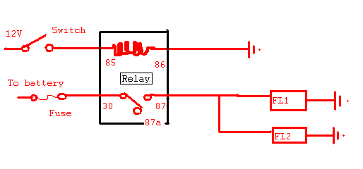
I presume the relay is an SPDT type. If so you should have the following poles on the bottom:
85 - one side of the coil
86 - the other side of the coil
30 - common
87a - normally closed
87 - normally open
You should connect as follows:
85 - 12V live from switch
86 - earth
30 - 12V live from battery (there should be an appropriate fuse between the battery and relay)
87a - nothing
87 - output to the fog lights
If the terminals are labelled differently post up a real close up of the diagram on the relay and the terminals.
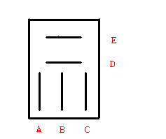
They are labled 1,4,2 on the top three which are all side by side not staggered...and 3,5 at the bottom side by side..it is napa part number AR606

Going from the picture at the top I think the following applies. I have relabelled the terminals as I can't see which number goes with which in the above photo.

A and C appear to be the two sides of the coil. You can check for a circuit using a multimeter (should be near infinite resistance between them). If they are there should be 12V live from the switch connected to one and earth to the other. Doesn't matter which.
E appears to be the common terminal and fused 12V from the battery should be connected here.
B and D then are the normally closed and normally open terminals. I can't tell from the diagram which is which. There should be a circuit between normally closed and the common terminal when no power is applied to the relay. When the coil is energised there will be a circuit between the common terminal and the normally open terminal.
If you mix up B and D all that'll happen is the fog lights will be on when the switch is off and off when the switch is on. So trial and error might be the quickest way forward.
iblis] wrote:
br>A and C appear to be the two sides of the coil. You can check for a circuit using a multimeter (should be near infinite resistance between them).
The coil should have a resistance less then 500 ohms. I would expect it to be in the 40-120ohm range, but it will vary from each model (and even from part to part)
-------------
Kevin Pierson
KPierson wrote:
iblis] wrote:
A and C appear to be the two sides of the coil. You can check for a circuit using a multimeter (should be near infinite resistance between them).
The coil should have a resistance less then 500 ohms. I would expect it to be in the 40-120ohm range, but it will vary from each model (and even from part to part)
Actually yes, I must have been reading the wrong scale on the multimeter.


