’86 honda civic si fan wiring
Printed From: the12volt.com
Forum Name: Vehicle Wiring Information & File Requests
Forum Discription: Request Car Alarm, Car Stereo, Cruise Control, Remote Starter, Navigation, Mobile Video, and Other Vehicle Specific Wiring Info, Manuals, Tech Tips
URL: https://www.the12volt.com/installbay/forum_posts.asp?tid=136616
Printed Date: April 27, 2024 at 6:10 AM
Topic: ’86 honda civic si fan wiring
Posted By: geezrx
Subject: ’86 honda civic si fan wiring
Date Posted: May 09, 2014 at 8:39 PM
Vehicle has electric fan with thermo sensor control in bottom of radiator. I want to install an illuminated switch to manually overide this sensor when desired. The switch I want to use is a rear defroster switch from the same model car as seen in the picture below
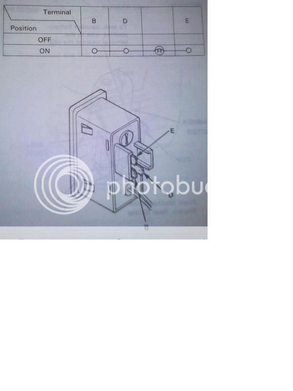
I know from trial that I can simply jumper one wire of the thermo sensor to terminal B & one to terminal D on the switch and it will allow bypass as desired...however, as I am "electrically challenged" I'm concerned that this would not be the correct/safe way to accomplish this. Below is the circuit schematic from the Honda Electrical Troubleshooting Manual for my vehicle
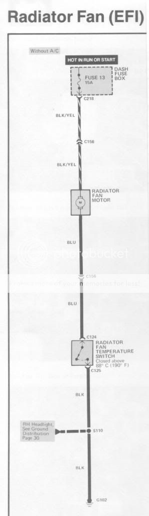
Taking into effect that I struggle with schematic diagrams, could someone detail a correct and safe wiring plan to implement the above switch into this circuit on my non-air conditioned vehicle that would in fact allow illumination on terminal C in the "fan on" mode? Thanks in advance for any help given!
------------- Skip
Replies:
Posted By: geezrx
Date Posted: May 10, 2014 at 9:22 PM
OK...sorry,just realized that the last statement in my original post should have read "allow illumination on terminal E...not C.
-------------
Skip
Posted By: oldspark
Date Posted: May 11, 2014 at 4:43 AM
Being a rear demister switch it may handle the fan current, but you'll need a relay anyhow...
Use a typical 30A relay. Wire its NO contacts (30 & 87) across the Temp Switch. That can be done between the fan's GND wire and chassis or other electrical GND if that's easier (and cooler & cleaner etc).
The demister switch B to IGN +12V (eg, Fuse #13); D to relay 86, and E to GND as well as relay 85 to GND.
The advantage with that method is that it's an add-on (ie, no cut & break of the existing wiring) whose failure should not impact normal/standard fan operation, and there is no high current thru the demister switch.
Posted By: geezrx
Date Posted: May 11, 2014 at 8:02 AM
Thanks for the reply oldspark. I'll purchase a relay and wire this up as you suggest.
Skip
-------------
Skip
Posted By: geezrx
Date Posted: May 11, 2014 at 5:40 PM
"Electrically challenged" strikes again! In the course of trying to buy a relay I am presented with the option to purchase a relay socket harness "with or without" a diode for the coil. It states this is beneficial if the relay will be controlled by an ECU. My vehicle has an ECU so...I read the description/use for diodes on here and get that it is a one way current "valve" but have no inkling whether I need one in this setup or not...anyone care to enlighten me?
Skip
-------------
Skip
Posted By: oldspark
Date Posted: May 11, 2014 at 11:55 PM
Sure. Tho your car has an ECU, it is not an ECU switching the relay.
And it's a (mechanical) switch doing the switching, hence not electronic as in ECU, computer, digital or analog circuit, etc.
However, tho there is no harm including such "spike suppression" diodes, many hereon claim to never have witnessed any damage by NOT including one - even when energised by ECUs etc.
I'd argue in your case it is optional but not necessary - ie, if it costs extra or adds inconvenience, forget it.
In some cases the spike might effect other circuits. I have seen LEDs or dash bulbs flicker in response to spikes on their supplies, and have read or heard of VERY RARE cases of damage - eg, a remote light or horn relay blowing an ECU or radio etc. However I'd argue those cases involve sub-quality ECUs & amps etc.
The one thing I argue against is relays with inbuilt spike protection diodes. IMO it is much better to supply the diode externally. You can therefore add your own or replace a blown diode, and do not have to worry about which end of the coil is +ve or -ve. [Hence the convention with (old style?) Bosch/Hella etc relays where 86 is coil +ve and 85 is coil -ve (GND). To connect those the other way for a relay with inbuilt spike diode means a short from +12V to GND thru the diode and that's not the sort of smoking session most people look forward to.]
Modern relays avoid such polarity issues. They use resistors etc instead of diodes, else make the designer/user mount the diode as part of the relay's wiring base or harness.
A bit more (optional FYI) detail...
The diode is there to prevent voltage spikes that could damage other electrics - eg, electronics.
The spike occurs when the the coil is de-energised - ie, you switch off the relay - IOW open the coil circuit. The coil tries to continue its current flow and therefore generates a big voltage spike.
Such spikes are commonly up to 200V but almost always below 400V for 12V & 24V systems. Hence 1N4004 or 1N4007 diodes are typically specified for "spike quenching" of coils up to 500mA.
A "backwards connected" aka reverse-biased diode conducts when the spike exceeds ~0.7V, hence "clamping" any (say) 400V spike to between 0.7V below GND (ie, -0.7V since GND = 0V = zero Volts) and 0.7V above the relevant +ve supply - eg, the +12V supply (which is usually 12.7V on a full battery and typically up to around 14.5V when driving/charging).
All automotive 12V electrics should handle such a range.
In early electronic and digital car days, and more recently with cheap or pathetic designs, manufacturers may not have included suppression for spikes. However these days all +12V power inputs should handle (say) up to +16V steady-state, and spikes up to 400V etc.
Similarly any output that might be expected to drive a relay should have inbuilt spike protection - ie, a $0.05c reverse biased diode ACROSS its output(s).
Having said that, I still see the occasional "modern" product that specify that YOU must add the diode if driving a relay. (Like wth did they expect us to be using - a MOSFET or solid-state relay?)
Sorry if the above got a bit much. In retrospect it's all so easy... Once you realise a diode can only conduct ( conventional current in the direction of its circuit symbol arrowhead (... and that the line on a real diode is the same end as the circuit symbol ie -->|-- ie so current can only flow out of the line end; the line (or brick wall) stops current flowing in from that end, you can begin to analyse and figure out your own use for diodes. (See the Diodes link at the top of this page.)
Posted By: geezrx
Date Posted: May 12, 2014 at 8:46 AM
Thanks again oldspark. You answered my question and educated me at the same time...I like that!
Skip
-------------
Skip
Posted By: geezrx
Date Posted: May 13, 2014 at 12:15 PM
If I am understanding your instructions correctly, oldspark, my schematic of the circuit I will construct would be as shown below?
 ------------- Skip
Posted By: oldspark
Date Posted: May 14, 2014 at 12:53 AM
Yes, that is correct.
Congrats!
FYI - more learning (trivial)...
No need to "break" non-connected crossing wires.
The convention is that any "cross" is NOT joined; all joins are "T" junctions (see 3a in the pic below).
That may be best illustrated by Wikipedia's Circuit diagram's pic:

We used to use crossroads and bridges/overpasses to signify joints and non-joining wires. That got too tricky or messy to draw.
Then came dotted or not for joined & non-joined. But the dots got lost in reproductions - photocopies etc.
Hence now the lower practice - all joins are T's. Note that old dotted/joined crossroads (1a & 1b) now have 45-degree deviations to produce the (angled) Tees (1c).
The latter is very tolerant to reproduction problems.
(Of course for OUR diagrams, we do as convenient! .. providing it's no ambiguous!)
Your "continuous" red wire is probably easier to draw, AND it conforms to the latest "standard". (Geez you're good! What is it with these people that reckon they're noobs or " struggle with schematic diagrams" - IMO they often seem to underestimate themselves. However caution is always advised, hence IMO never any harm asking for ideas, confirmation, etc.)
The "circuit operation" is easier to see if your upper & upper-right relay connections went downwards. It might then be more obvious that the upper 87 to vertically under 30 to GND is merely a parallel contact (switch) to the existing thermo switch. IE - if either are closed, then the fan operates (assuming the fan motor + has +12V to it).
That can be difficult else messy to do using "wiring schematics" - ie, circuit diagrams that use physical representations of components (switches, relays etc).
My diagrams are usually "circuit" diagrams where "pins" or terminals may be located anywhere in order to make analysis easier.
Maybe 12 to 24v automatic swap is a good example - ie compare Ween's "schematic" and my "circuit" in the 8th & 9th posts. Ween's is easier for wirers whereas (IMO) mine is easier to figure out how it works.
Note also that my circuit does not specify relay pins - I leave that up to the builder, hence they decide if they want to use Bosch type (30, 85, 85, 87 etc) or micro-DIN (1, 2, 3, 5 etc) or other relays.
Posted By: geezrx
Date Posted: May 14, 2014 at 10:23 AM
I see what you mean. It is easier for me to "see" the circuit path in my revised drawing (all done in "Paint" which is so-so for this).

Again, the help is greatly appreciated!
Skip
------------- Skip
Posted By: oldspark
Date Posted: May 14, 2014 at 7:21 PM
LOL - me too - MS Paint. Hence the reason I haven't done any drawings since my upgrade from Windoze 2000 to 7 last year. MS Draw was so much easier to use.
I do have other packages for circuit diagrams etc but rarely use them...
Thanks for the appreciation.
Posted By: geezrx
Date Posted: October 19, 2014 at 10:16 AM
Back again and hoping to get some advice on an upgrade to this setup. Everyone was so helpful with past information! The setup that exists is as shown previously in the post and here again for convenience:

The OEM fan is failing and never did provide enough airflow to effectively cool the system properly so I have now replaced the old radiator with a new all aluminum one and have mounted dual Flex-a-Lite fans (8a draw each and wired in parallel) and want to incorporate them into the existing wiring scheme shown above. The "fuse 13" is 15a. I'd appreciate input on how to best alter this setup, if necessary, to accommodate the new fans. Thanks in advance for the response!
Skip ------------- Skip
Posted By: Ween
Date Posted: October 19, 2014 at 11:32 AM
Hi,
I'd modify the wiring as follows...
Convert manual override switch to switch a ground;
Term B...ground, Term E...ignition, Term D...switched ground out.
Rewire and add an additional relay for fans, one relay per fan
(coils in parallel);
Term 30...battery power fused (15-20A),
Term 87...fan positive, ground negatives,
Term 86...fuse 13 (switched power),
Term 85...negative from override switch and fan thermo switch.
Each relay switches one fan. The thermo switch only carries relay
coil current increasing its reliability.
Mark
Posted By: geezrx
Date Posted: October 19, 2014 at 6:20 PM
Thanks for the response WEEN! Well, I don't know if I've got it or not but after cogitating on it a bit I put together this new schematic -

If I'm pumpin' swamp water here don't hesitate to tell me...It's always a struggle for me but once it gels in my head I can typically get the job done! Can't at this point say for certain that the "gel" mightn't actually be "mush" but hopefully I'm in the vicinity? If this IS the ticket to allowing the simple thermostatic switch to cycle the fans automatically AND allow me to cycle them manually if I feel the need, while insuring that the circuits are correctly wired for safety and long term reliability...Great! Once again, I sure appreciate the information and help! ------------- Skip
Posted By: Ween
Date Posted: October 19, 2014 at 6:29 PM
You're close, have the thermo switch have ground on one side instead of the switched power and you're good. The thermo switch is already set up from the factory to supply the ground you need.
Posted By: geezrx
Date Posted: October 19, 2014 at 8:00 PM
Since it hasn't gelled (obviously!) I guess I took your statement...
" Term 85...negative from override switch and fan thermo switch."
too literally? My next assumption will be:

Sorry, I'm sure it's frustrating for you who are proficient in this magic to deal with those of us who aren't ! I again, really appreciate your time and patience. ------------- Skip
Posted By: i am an idiot
Date Posted: October 19, 2014 at 8:29 PM
One of the first pictures you posted is kind of misleading. The thermal switch at the bottom of the relay grounds the coil of the fan relay. It is showing you the contacts within that relay which when the thermal switch grounds and energizes the relay, then the contacts shown on the picture provide the high current needed to spin the fan.
Posted By: Ween
Date Posted: October 19, 2014 at 8:48 PM
Close again, the '+' lead of the thermo switch connects to term 85 of the relays, not term 86. The thermo and override switches are to be wired in parallel.
Posted By: i am an idiot
Date Posted: October 19, 2014 at 10:09 PM
E on switch to 12v. B on switch to Ground. D on switch to the wire on the thermal switch. If you do not want it to illuminate when the thermal switch turns it on, you will need to put a diode on the wire between the new switch and the thermal switch.
Posted By: geezrx
Date Posted: October 20, 2014 at 1:28 AM
To Ween and i am an idiot...thank you both for your immense patience!! I think (I hope) that the "ground switched devices" concept (right?) is just beginning to gel...sorta. Hope "3rd times a charm" and latest scheme is correct?

If I follow correctly what you're saying iaai, the override switch light will energize anytime the fans are running without the addition of a diode. If correct, that's actually desirable as then either way it will let me know that the fans are either cycling (thermo switch mode) or on continuous (manual switch mode). ------------- Skip
Posted By: howie ll
Date Posted: October 20, 2014 at 2:42 AM
Actually I've been looking at this and I believe you can eliminate the relays, just take the blue wire between fan and thermal sensor and ground it.
-------------
Amateurs assume, don't test and have problems; pros test first. I am not a free install service.
Read the installation manual, do a search here or online for your vehicle wiring before posting.
Posted By: Ween
Date Posted: October 20, 2014 at 4:40 AM
Hi Howie,
The reasoning behind the relays is to allow the switches to carry less current, increasing their reliability, as well as limiting voltage drop issues by being in closer proximity to the loads and source. No high current wiring to the override switch. The dual relay setup allows one system (fan, relay, associated high current wiring) to possibly fail while not affecting the other, affording the vehicle some cooling while at slower speeds. Also the independent relays to each fan will appreciate switching a lighter load.
Hope this explains my circuitry changes.
Mark
p.s....too early here, shouldn't be awake for another hour.
Posted By: howie ll
Date Posted: October 20, 2014 at 8:01 AM
Points taken, it's just that a million years ago we pulled this stunt on Jensen Interceptors, seem to remember just a green Hella pull switch and some wiring.
-------------
Amateurs assume, don't test and have problems; pros test first. I am not a free install service.
Read the installation manual, do a search here or online for your vehicle wiring before posting.
Posted By: Ween
Date Posted: October 20, 2014 at 8:24 AM
Would a Jensen have Lucas 'prince of darkness' wiring?
Posted By: geezrx
Date Posted: October 20, 2014 at 9:11 AM
Speaking of "prince of darkness" wiring...my first two vehicles were Austin Healey 3000's with Lucas electrical systems...hmmm, maybe I see some deep seated issues relating to my lifelong lack of comprehension of electrical problems! I've always had a suspicion that electricity and it's use is one of the "Black Arts"  
And so Great Wizards...any comments on my third try at getting a working schematic to go by, as posted on bottom of previous page? ------------- Skip
Posted By: howie ll
Date Posted: October 20, 2014 at 9:17 AM
Oh yes hemi engine and Chrysler gearbox, aluminium body, built in the UK. Mopar engine bay wiring into Lucas interior wiring. Jaguar switches, Smiths gauges, at least Smiths got out of that market, now US based and make the displays for most US aircraft.
Also first non SUV with 4 wheel drive and first vehicle with ABS.
At 130 + you could watch the fuel gauge needle moving!
PS Lucas now make the injectors for most diesel vehicles, e.g. Mercedes.
Most of the wiring looms nowadays come from China with locally made AMP or Molex connectors.
-------------
Amateurs assume, don't test and have problems; pros test first. I am not a free install service.
Read the installation manual, do a search here or online for your vehicle wiring before posting.
Posted By: howie ll
Date Posted: October 20, 2014 at 9:25 AM
Let me demolish some myths! Any British sports car actually any British car from the 60s was a POS on all bar brakes and suspension.
Probably the world's worst build quality with the world's best suspension, just about every modern car suspension can be traced back to MacPherson's work for Ford UK or Colin Chapman's work (Lotus).
The current myth is VW reliability, can I tell you stories there.
Insisting on coil packs with cheaper insulation, next queues of Audis awaiting rescue, Mercedes, 98-05 shoving the gearbox oil cooler rad into the water rad then announcing it was the fault of ZF.
And as for the build quality of US vehicle interiors....
-------------
Amateurs assume, don't test and have problems; pros test first. I am not a free install service.
Read the installation manual, do a search here or online for your vehicle wiring before posting.
Posted By: Ween
Date Posted: October 20, 2014 at 6:12 PM
The last schematic/diagram is all good.
Posted By: geezrx
Date Posted: October 20, 2014 at 6:41 PM
Thanks again for the patient help and directions! About mid morning today, as I sat looking at the last schematic I rendered in the wee hours of the morning...the light came on...I could see how it all worked. Putting together a supplies list now to get the necessary items and get this project behind me. This is a great forum with helpful, knowledgeable folks!
-------------
Skip
|