I am trying to get an Avital 4103 to work on my 2004 Ram 1500. I have installed many remote starts in the past, from bulldog to Fortin. This is my first Avital install and maybe my last. Most confusing wire list and zero help from Avital. Can anyone help with what wires are required and where to land them?
Gray key? transponder chip - need a bypass module
Factory Alarm? need some relays and resistors
I'll assume no to both as you did not mention a bypass module ( and you have done R/S's before ).
Avital 4103 and 2004 RAM 1500
H1/1 LIGHT GREEN/ BLACK FACTORY ALARM DISARM not used
H1/2 GREEN / WHITE FACTORY REARM not used
H1/3 YELLOW (+) IGNITION OUT (TO ALARM) not used
H1/4 WHITE/ BLUE (-) ACTIVATION INPUT not used
H1/5 ORANGE (-) GROUND WHEN LOCKED not used
H1/6 BROWN (-) HORN OUTPUT DARK GREEN/ PURPLE (-) @ STEERING COLUMN HARNESS
H1/7 RED / WHITE (-) TRUNK RELEASE OUTPUT not used
H1/8 BLACK GROUND Chassis Ground
H1/9 WHITE (+/-) LIGHT FLASH Set to (+) and use a relay as per diagram :
https://diagrams.marktoonen.nl/DOWNLOADS/32277_RAM-FULL-SIZE-PICKUP-_CHRYSLER%20PARKING%20LIGHT%20DIAGRAM.pdf
H2/1 BLACK/ WHITE (-) NEUTRAL SAFETY SWITCH INPUT Chassis Ground ( auto trans! )
H2/2 VIOLET/WHITE TACHOMETER INPUT WIRE dk. blue/gray ac @ PCM, orange plug, pin 34
H2/3 BROWN (+) BRAKE SWITCH SHUTDOWN WIRE WHITE/ TAN (+) @ SWITCH ABOVE BRAKE PEDAL
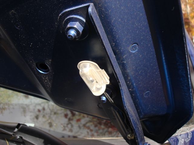
H2/4 GRAY (-) HOOD PINSWITCH SHUTDOWN WIRE to kit supplied hood pin
H2/5 BLUE/WHITE (-) 200mA 2ND STATUS/REAR DEFOG not used
4-pin satellite harness diagram
1 BLUE STATUS OUTPUT not used
2 ORANGE (-) ACCESSORY OUTPUT not used ( might be used w/relay - see Note 8 below )
3 PURPLE (-) STARTER OUTPUT not used
4 PINK (-) IGNITION OUTPUT not used
Heavy gauge relay wiring diagram
1 PINK (+) (30 AMP) OUTPUT TO IGNITION CIRCUIT PINK/WHITE (+) @ IGNITION SWITCH HARNESS
2 PURPLE (+) (30 AMP) OUTPUT TO STARTER CIRCUIT YELLOW (+) @ IGNITION SWITCH HARNESS
3 ORANGE (+) (30 AMP) OUTPUT TO ACC CIRCUIT DARK BLUE (+) See NOTE *8 @ IGNITION SWITCH HARNESS
4 RED (+) (30A) HIGH CURRENT 12 INPUT RED (+) @ IGNITION SWITCH HARNESS
5 PINK/WHITE (+) PROGRAMMABLE OUTPUT Pink/Lt. Green (+) @ ignition harness
6 RED (+) (30A) HIGH CURRENT 12V INPUT RED (+) @ IGNITION SWITCH HARNESS
NOTE *8 On some Full Size Trucks with Climate Control it may be necessary to connect (3) extra Accessory wires.
PINK / YELLOW 16 gauge & PINK / YELLOW 14 gauge and the DARK BLUE Accessory #1 to turn on the A/C Compressor.
Door lock harness, 3-pin connector
1 BLUE (-) UNLOCK OUTPUT to Directed 451M Door Lock Module
2 EMPTY NOT USED
3 GREEN (-) LOCK OUTPUT to Directed 451M Door Lock Module
You could use a couple of relays & resistors and this diagram :
https://diagrams.marktoonen.nl/DOWNLOADS/14301_RAM-FULL-SIZE-PICKUP-_DODGE%20RAM%2004-05%201%20WIRE%20JBS%20UNITS.pdf
You will need to make a programming changes to the 4103 for Tach Mode and Horn Honk.
-------------
Soldering is fun!
Turns out I have been fighting a bad hood pin the whole time. The wiring info posted is correct
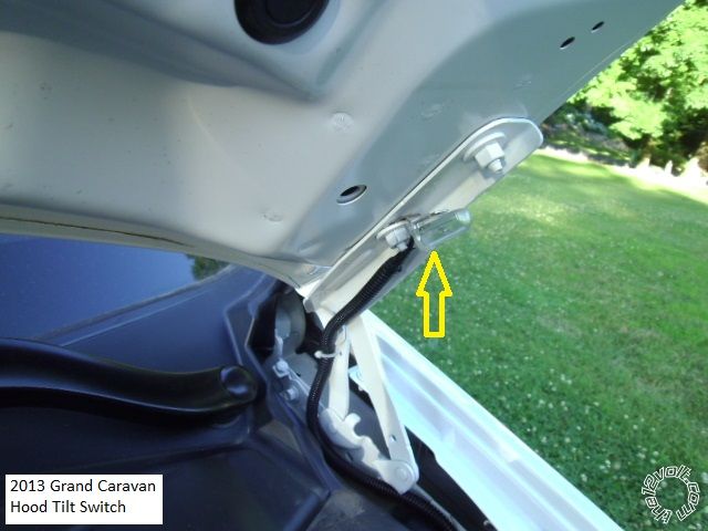
And to add insult to injury, that new hood pin will go bad in a few years, depending on the weather and road salt. Might think of replacing it with a tilt switch. They last a lot longer and you don't have to drill any holes.
-------------
Soldering is fun!