I have a 2006 Ford Explorer XLT 4.0, and it has a cloth tan interior. I am switching to a black interior, as well as black leather seats.
I just bought some seats out of a 2007 or 2008 Explorer EB or Limited model. As far as I can see from the diagrams ive pulled, 2006-10 are all the same.
Heres my stock setup:
Drivers seat: 6(?) way power, manual recline, airbag.
Passenger: Manual, airbag
Replacement seats:
Driver: 10 way power, heat, airbag and I THINK memory function
Passenger: 6 way power, heat, airbag. (This one is done and wired, except heat)
My Explorer had a harness coming up for each seat, wires are the same, except mine are missing some from the leather ones. The passenger seat needed 3 additional wires, power, ground, and a heat wire which would tie into the heated seat module if I had all that. Im not worried about that, but would love to add it at a later date.
The drivers seat had matching wires as well, but the seat has an additional thin wire in the harness which is yellow with a green or blue stripe. Id have to go back and double check to be sure.
There is also a second female plug in the bottom of the seat with more wires, which my Explorer does not have. I am assuming this is what ties the memory and heat controls, since the heated seat buttons (if equipped) are in the radio trim bezel.
All I am worried about is getting the power seats to function. Passenger side is done as I said, but I am stumped on the drivers side. Plugging the harness in does not work. Its needing another power and/or ground somewhere, and im wondering if the memory module is hindering it from working right now, maybe it needs power?
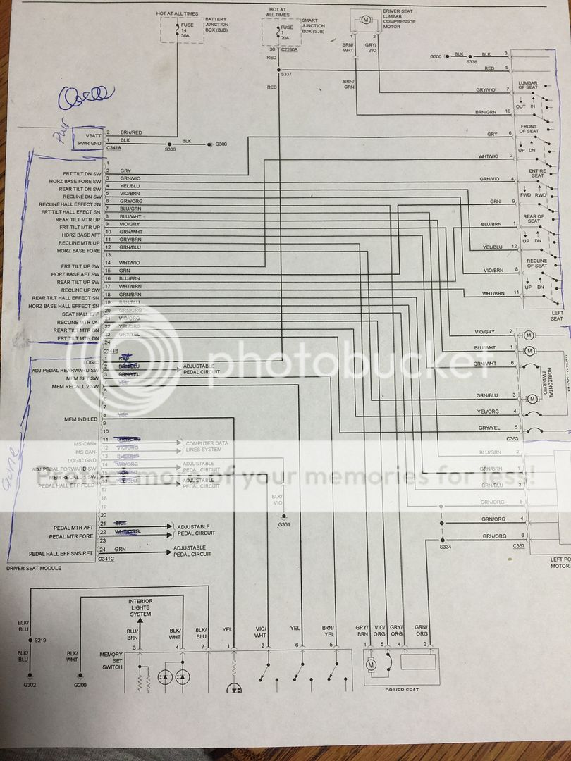
I have some diagrams I saved from ARRC:
Drivers side 10 way power circuit diagram:

Memory circuit diagram:

Heated seat diagram:

-------------
2006 Explorer XLT
2009 Ford Fusion SEL
So I brought the seat inside and set it up on the table. Screw it, I need light and heat to figure this out, lol.
This is where I am at now:
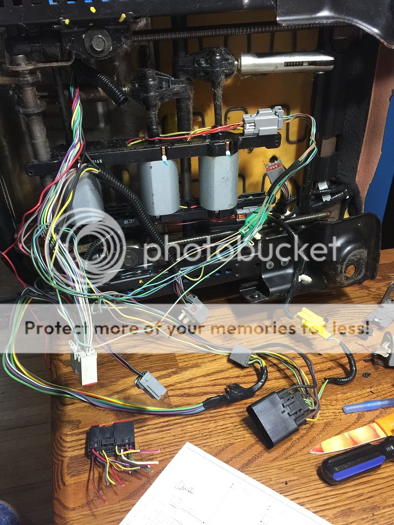
The second harness I spoke of which had a few larger gauge wires in it was all tied in to the memory system. The large wires were grounds, and were controls for the adjustable pedals. The rest was communication and such, I cut all that out.
Exposed most of the wiring so I can see whats what, and what goes where.
Maybe with it like this, it will be easier to help me out. I am stumped now, but have a much better understanding of whats going on. However, it confuses me how the seat works. There was a large power and ground going in to the memory module. In the middle connector, there were 6 large wires that plug into the left side (If youre looking at the front of the seat) of the 3 seat motors. (Plugs into a harness that splits it up between the three units).
The same connector coming into the module has 5 thin gauge wires going to the other side of the motors, but two of the wires splice together, and then come out as 3, so its 6 wires again.
There are a few more wires in that same harness which plug into a plug that goes up into the back of the seat, so i'm assuming thats the recliner motor. There are 8 wires in that connector.
Somehow these wires need to be spliced together, right? This is where I am lost.
Here is the diagram I have printed out. The square with "gone" poorly written above it is the connector that I cut out. It was the one going into the memory module, which then went to a large female connector under the seat which I cut off as well.
-------------
2006 Explorer XLT
2009 Ford Fusion SEL
Schematics I have show a common battery feed (red) for the switch and drivers seat module as well as an additional battery feed (BROWN / red) for the drivers seat module. They also show a common ground (black) for the switch and module as well as a logic ground (BLACK/ orange) on the module.