samsung tv/dvd inverter when dvd on
Printed From: the12volt.comForum Name: Mobile Video, GPS, and Navigation
Forum Discription: Mobile Video Head Units, DVD Players, LCD and TFT Monitors, Navigation, GPS, PS2, PS3, XBox, etc.
URL: https://www.the12volt.com/installbay/forum_posts.asp?tid=137147
Printed Date: March 12, 2026 at 12:00 PM
Topic: samsung tv/dvd inverter when dvd on
Posted By: rajivkohli
Subject: samsung tv/dvd inverter when dvd on
Date Posted: August 24, 2014 at 3:51 AM
I'm using an inverter (300w) in my RV (Two 12v batteries are in parallel solar charged)
I'm using Samsung 22" TV (12v to 110 volts to 14v dc tv)
I'm using Samsung DVD/wireless with HDMI (12v to 110volts)
when I plug both of them in the inverter shuts off.
If I unplug the DVD.. The TV runs fine
if I only use DVD ... The inverter keeps running
I put both (TV on 150 watt inverter and DVD on 300 watt inverter off 12v) on different inverters and still the inverter plugged with TV turns off.
help.. I don't get it
I kicked off the generator (gas to a/c) and ran both
on electric and they ran fine)
I put a multimeter on. ..
Without anything plugged in. .12.8volts
with both inverters plugged in.. 12.0volts
-------------
alphabeta
Replies:
Posted By: i am an idiot
Date Posted: August 24, 2014 at 8:16 AM
You need a higher capacity inverter. Or 2 of them.
Posted By: rajivkohli
Date Posted: August 24, 2014 at 9:41 AM
But I thought I did
I have a sinewave 400w inverter for CLEAN POWER (i put the dvd on)
i have a regular 150w inverter (o put the tv on)
then
i switched then around... same results
..
what capacity do you think i should go with?
..
I have 2 deep cycle battery bank of 90 amps each (hooked in parallel... It is my understanding that I'll have 12v+ across the bank for a total of the 180amp/hrs.)
the TV draws only 3.5amps... not sure on the dvd though
how high a inverter capacity should I go?
-------------
alphabeta
Posted By: i am an idiot
Date Posted: August 24, 2014 at 10:42 AM
A 400 watt inverter is usually a 200 watt device. You need to read the continuous wattage output. Usually half of what they say they are. I recommend buying something that is twice the continuous output that your equipment requires.
Posted By: oldspark
Date Posted: August 25, 2014 at 10:32 AM
Is that 12V voltage at the battery or inverter input? Make sure the DC feed from the battery is big enough. A 300W inverter at full power means about 30A at 12V. And inverters have a minimum voltage requirement; some cut out at ~10.6V to protect batteries but others may cut out at higher voltages.
A 110V TV at 3.5A = 385VA. The Wattage depends on power factor, eg if pf = 0.6, then 385VA x 0.6 = 231Wl pf = 0.8 => 308W. But if that 3.5A is at 12V, then its 12 x 3.5 = 42W.
But I'd expect the "12V" or 14V TV to mean automotive 12V (ie, up to ~14.5V with engine running) so it shouldn't need an inverter. If it really needs regulated DC or 14V etc, then find out its current draw - a dc-dc converter may be the way to go (certainly more efficient than an inverter).
Old TVs (pre LCD etc) usually had large inrush currents on their AC supply.
The usual rule is to size the inverter based on TWICE the power requirement of the loads; 3x if it's a motor; less if the load is is inrush limited.
Here in Oz all ratings are steady state. EG - a 300W inverter means 300W long term. And by definition, a 300W inverter or load (sometimes clarified as being 300W RMS) with have a peak twice as high - ie, 600W peak. (Though 600W peak can mean 600W "RMS" for a short period of time - eg a few cycles or seconds. Unfortunately Wattage and peak ratings are often poorly defined.)
But stateside I believe an inverter's rating may be its peak which IMO is useless, but at least its steady-state or average or RMS should simply be half of its (peak) rating.
Posted By: rajivkohli
Date Posted: August 25, 2014 at 11:55 AM
Thanks much oldspark and "i am an idiot" :-) LOL funny handle.
..
Anyways..
1. Yes, I have 12.x Volts at the Inverter input
2. The Samsung TV has a 14v input (Meaning the transformer that came with it is a "step down: 11v - > 14v)
3. I prefer the Dc-Dc, but how where will I get one that will step up 12v->14v (Any recommendations?)
So, I did buy a COBRA inverter 1600w (800w continuous) that was on sale for $59 (69-10 rebate). It worked fine. But not the optimum solution.
I prefer DC all the way, everywhere -> I have in my motorhome (Btw, I'm driving from Anchorage, Alaska to NJ a total of 6000 miles - Just that I got a small engagement in Seattle, WA so I'm parked here for 2 months) .... Slow Cooker,Popcorn, water-heater rod, camera/phone chargers,.....
I have been off the grid (Off/on since 10/2013, and continuous since 5/14) for a few months now ... 2 100w / 30A panels feeding 2 Batteries (I think, I just repeated myself)
Should I consider 24V battery (2 12V in Series)? Just that I don't want two systems...The only reason I thought about it is for step down from 24V to 14v maybe still plausible in compared to stepup from 12v to 14v.
Also, I did another test.
To recollect:
1) I have a small Deep Cycle battery bank - 2 Batteries
2) I have the standard engine Cranking Battery - 1
So, I used the 400w converter on the 2-Battery Bank and the 150 W converter on the engine battery
DVD to House Batteries (400w)
TV to Engine Batteries (150w)
and it worked fine
Then I switched the inverters around
Worked fine
Then I also switched the DVD/TV around
Worked fine.
Why? I wanted to see what the load of TV and DVD was individually on the lowest requirements.
So, I guess the 150w (So practical would be 75w)... So according to calculations --
TV must be
On A/c: (308W) "A 110V TV at 3.5A = 385VA. The Wattage depends on power factor, eg if pf = 0.6, then 385VA x 0.6 = 231Wl pf = 0.8 => 308W"
I'm not clear here... By A/C.... Do you mean direct plug in without step-down transformer to 14v or direct.... It shouldn't matter... In the end the TV is to receive 14v
On DC: (42W) "But if that 3.5A is at 12V, then its 12 x 3.5 = 42W)
Thanks in advance... You guys have been very very helpful.
I haven't used forums/net-groups for eons.
Also, another Q - I'm using 3 mini cameras that are ON all the time. I use them for side-view mirror and rear view (Thus covering the side doors)... I'll soon use laptop and one TV/monitor all the time as the company (Microsoft) will allow me remote access into work. This will save me commute time / money and I can park anywhere. The assignment is 3 months, max.
I have 2 solar panels (100w @ 30A each)
I have 2 deep cycle batteries (90A, 12V in parallel).
All lights are LED (about 10... used intermittently)
I have 2 ceiling exhaust fans)
The heater blower fan (This seems to be a big draw everytime it runs... Maybe cause it is old)
Q: Do you think i should add another battery to the bank?
My apologies for adding to the original thread Q
-------------
alphabeta
Posted By: oldspark
Date Posted: August 25, 2014 at 1:19 PM
Avoid 24V. There's little difference between converting up from 12V or down from 24V but 24V is a problem with 12V alternators and solar arrays.
So the TV is 14V AC, not DC. That could mean it's about 18V DC internally. Any possibility of getting to that internal DC output? But you'd have to make sure the TV does not use the 14V AC for timing - tho I doubt that.
I'd suggest reconsidering your loads. Get a (automotive) 12V DC TV (LED LCD) & DVD player etc. Same for other loads as far as possible.
Generally you find that's the cheapest option - especially when solar is used.
As a guide, there are naked 5A buck/boost(down/up) dc-dc converters for as low as $8.
Except for having independence from your main cranking battery (so it isn't flattened by your loads), IMO there's not much point getting an extra battery if your solar (or other charging) can't keep up. Tho an extra battery might help - ie, less current from each or more capacity between charges etc - it means 3 short lived batteries if they aren't charged properly. Plus the extra hassle or risk of yet another parallel battery. (Bigger batteries are better than paralleled batteries.)
But that depends on the charging regime. If your engine (alternator) can be used to charge in cases of solar shortfall, then IMO the more batteries the merrier tho that also depends on whether paralleling occurs with unmatched batteries or they discharge independently.
A 90AH C20 battery should provide 4.5A for 20 hours, or probably 8A for 10 hours (80AH @ C10) etc, but consult you battery datasheets.
And unless battery life isn't an issue, I suggest discharging deep cycles no more than 50% (20% for crankers).
FYI - I often deal with multi-battery setups where batteries are paralleled only when charging and therefore battery matching is not an issue - eg, a main 80AH wet cell for cranking etc; a 60AH AGM for fridges or audio, a 7AH AGM for car computers etc.
But permanently paralleled batteries should be matched and symmetrically connected. EG, 2 collocated batteries from the same manufacture batch with the same history (charge/discharge) interconnected with matching +ve & -ve cables with the +12V take off from one and the -ve take off from the other battery.
And care is required with paralleled AGM batteries - a fault in one can lead to a thermal runaway. (Same too for series AGMs.)
It's usually simple in principle to connect all batteries for charging - ie, off the alternator. (But be aware, some alternators won't handle very flat batteries or too high a load.)
If the alternator's charge-light circuit can't be used to control a (master) battery isolation relay then single low current voltage sensing or "smart" battery isolator can act as a master to drive one relay per extra battery. When not charging the relays open and isolate all batteries from each other. Of course some batteries may be kept permanently paralleled whether by manual control of their relay(s) or buy omitting the relay (& its current drain) and using normal hardwired interlinks which are disconnected when the batteries are to be left unused for long periods (ie, maybe days else weeks).
I doubt your solar panels are 30A each unless they are only 3-4V output. I'll assume that should be between 3A to 5A depending on the output voltage (most "12V" panels output between 17V to 27V or thereabouts).
But with batteries - and especially solar - it is imperative to minimise all loads. I replaced my $145 fridge/cooler with a $1450 fridge because that proved cheaper than buying more panels and battery(s) etc. (Plus that it would cool to -19C in +45C ambient whereas the cooler (which took over 10x the power) merely cooled to 20C below ambient.)
Posted By: rajivkohli
Date Posted: August 25, 2014 at 3:04 PM
Got it .... Drop the idea of 24v
Thanks for clearing the 14v (A/c input) to potential 18v (DC Internally). Didn't realize that
I'll just buy another DC Tv. The one I'm thinking of is
https://www.amazon.com/Supersonic-SC-2211-Widescreen-1080p-Digital/dp/B0066AE4M8/ref=cm_sw_em_r_dp_zr4-tb0X6XGAA_tt
I already bought these naked step-up
https://www.amazon.com/gp/product/B00JUHW6PG/ref=oh_aui_detailpage_o01_s00?ie=UTF8&psc=1
https://www.amazon.com/gp/product/B008BHAOQO/ref=oh_aui_detailpage_o03_s00?ie=UTF8&psc=1
I bought this to closely monitor Usage (Esp..Amps)
https://www.amazon.com/gp/product/B00EYZS6R6/ref=oh_aui_detailpage_o07_s01?ie=UTF8&psc=1
I do have a Relay/Solonoid between Alternator/House Battery. When the RV is running, the alternator charges the house battery at 13.5v (Not sure the amps, it pumps). It cuts off the house batteries from the main once I shut the engine off.
Unfortunately, I DON'T have matching batteries. Though they are brand new. I bought one new and a friend gave me another one from his boat. However, I didn't realize that my solonoid had gone bad and ended up throwing his battery away (While traveling through Canada). Both are deep cycle BUT one is a high end "Intrastate" and the other is a "Walmart" - Enough said :-) on the quality. But, for now they are sufficing and meet my needs.
You are right on the Solar Panels amps throughput. The controller can handle a max of 30amps. Here's the kit I bought
https://www.amazon.com/Solar-Panel-Starter-100W-Monocrystalline/dp/B00BFCNFRM/ref=sr_1_1?ie=UTF8&qid=1408994910&sr=8-1&keywords=renogy+solar+panel+kit
I also bought one of these so I can closely monitor the battery (I wonder how much energy is used in monitoring, also :-( )
https://www.amazon.com/gp/product/B00IY5L9UI/ref=oh_aui_detailpage_o04_s00?ie=UTF8&psc=1
Thanks much -
PS: Not sure if I hit "Post Reply" as I got distracted at work. My apologies, if u c it twice... But, i don't think so I did
-------------
alphabeta
Posted By: oldspark
Date Posted: August 26, 2014 at 6:14 AM
Hmmm - a "FULL HD" with only 1366 x 768 resolution. It'd be illegal to call that Full HD here - Full HD is 1920 × 1080. We don't care if it can handle a 1080i signal, it's the display that counts, and obviously there must therefore be 1080 vertical pixels - not a mere 768 (that's only ~70% of Full HD!)
Alas that TV does not specify if "12V DC" means automotive 12V (eg, 8V - 16V etc) or a regulated 12V (typically meaning 12.0V +/- 0.5V). But usually a mere "12V DC" rating means regulated 12V (as with LED strips - something many car LED strip installers learn the hard way).
Nor does it specify its DC power or current - usually a maximum value though a nominal/typical value can be included.
No rating either for its AC consumption which could probably be used to determine a safe DC requirement - eg, 80W AC should mean 80W or less for DC, hence assume perhaps a max of 80W/11.5V = 6.95A hence 7A @ 12V; maybe a 10A @ 12V supply if applying the common "generally run at no higher than 70-80% of rated power/current".
Neither of those DC-DC converters are buck-boost. One can only convert to lower than its DC input and the other only higher. (Many have a 1.5V gap or loss - eg, from 12.0V can only produce below 10.5V or above 13.5V.)
For 12V regulated you'd need a buck/boost to provide 12V (+/-0.5V) for a normal car voltage of 12.6V to (say) 14.4V for a full battery & with engine running respectively, LESS voltage drops including the battery's internal resistance (if it is supplying the load) LESS the voltage drop as the battery discharges.
Hence typically assume a (say) 10.5V to 12.7V range on battery alone, or 10.5V to 14.5V including alternator etc charging, or maybe the "standard" nominal ideal of 8V to 16V (else 15V) to handle cranking dips and not uncommon initial charging voltages up to 15V and maybe 16V. (Not that operation as low as 8V may be impractical or uneconomical etc.)
Tho the Wattmeter is handy to confirm the actual load, IMO in many ways it's like an ammeter in a car - useless.
It will not indicate the condition of the battery per se though its voltage display will. IE - for vehicles, the best indication of battery condition is the battery terminal voltage. Current is essentially useless other than to show that you are charging the battery at a higher Amperage than its specs allow, or that it's taking excess current when it should be taking float current - eg, when fully charged, accept from 100mA to 1A for typical car batteries; maybe 2A for big batteries.
But no alternator limits the charging current in accordance with battery specs tho some newer vehicles could monitor battery current and hence drop the system voltage, but why bother with that cost and complication when a normal car battery should last well over 6 years despite the possibility of so-called over charging?
And your solar controller/charger handles 30A. That makes total sense! Assuming it's a linear device (not an MPPT) and the panal is outputing its max 100W at 20V, that's 100W/20V = 5A per panel - and an effective output at 14.4V of 14.4V x 5A = 72W.
But it's not unusual (here) for a 100W panel to produce 120W or more. (They tend to rate panels by typical max output, not the output for the odd exceptionally bright & clean air day etc. But lets assume their 5A output is 10A instead, that's 20A total and your controller handles 30A so no worries).
And Geez - solar costs have come down! When I started my own system, panels were $10/Watt - ie, $1000 for a 100W panel. (That's AUD$1000; probably USD$900 based on average exchange rates.) I was rapt to get 120W as 5 x 20W panels plus a ($22 DIY) controller for ~AUD$720.
Non-matched batteries... You'll find a lot of misinformation out there - eg, see my "discussions" with redheadedrod on mp3car.com (and tho on another topic, red was the reason I dumped mp3car).
For installations that are permanently paralleled (or in series), all batteries "must" be matched (for battery longetivity reasons if not safety).
Examples include series 12V batteries for 24V truck systems, and two 2-series 12V batteries paralleled for heavy 24V systems - eg, big machinery like Caterpillar machines which use equal inter-battery links and opposing take-offs ie +24V from one string's +24V and GND from the other string's most negative battery's -ve terminal. (String means the series components - eg, the two series 12V batteries.)
In fact Caterpillars etc usually also physically stagger the batteries in a 2 x 2 pattern ie so a string's +24V battery is top right and its -ve/GND battery is bottom left, thereby hopefully balancing out the string effect from hotter ambient temperature on the RH side and colder on the left.
And those four 2x2 batteries follow the same rule as any batteries in series or (permanent) parallel - if you replace one, replace all (as matched batteries).
A faulty battery will ruin the other batteries. EG - in parallel, a good battery will NOT hold up or preserve bad battery; the bad battery will ruin the good battery. (In fact a bad & good will usually kill the bad battery quicker. And if the batteries are AGM, thermal runaway can lead to fire or explosion.)
So now I've told you the normal rule of only combining matched batteries.
[ Even your TV remote etc is the same - don't mix new & old batteries, tho that's usually for overall battery life reasons and not safety! And tho that's the same in principle as our lead-acid batteries, care should be taken comparing such rues & behaviors. ]
Holy moo what a ramble this has become!
Anyhow, I've said why not or do not, and now I'm going say it is ok - IN CERTAIN CIRCUMSTANCES.
For paralleled batteries BEING CHARGED, it doesn't matter if they are matched. You can parallel 1.2AH with 120AH, new with old - and - AGM with wet or gel whether deep cycle or crankers PROVIDED they share the same charging characteristics.
Luckily "our" 12V wet & AGM batteries typically share the same (traditional) charging practice. EG - traditional alternators and solar chargers are set for charging at 14.2 to 14.4V. (The older 13.8V charging setting for 12V lead-acid batteries has been long superseded.)
BTW - your alternator charging voltage is too low!
13.5V is too low unless its (say) at idle speeds or has too many loads (maybe because initial battery charging current is too big for the alternator to handle).
The batteries must (eventually) get preferably 14.2 to 14.4V. (Like I said, the old 13.8V is long superseded - it's too low for acceptable or long battery life.)
That's to remove sulfates that form whenever the battery is not fully charged. The flatter the battery, the faster sulfates form, and they reduce battery capacity. But that's another story.
The 14.2 - 14.4V above is across the battery terminals - not at the alternator whichj may be outputing 14.6V or even 15.6V).
Maybe you are undercharging because the alternator is too small (during peak loads) or its brushes are worn or its regulator is faulty?
Except for "single-wire" D+ alternators, an alternator can be tricked into outputting higher voltages - namely by inserting diodes in its (regulator's) Sense line (to the battery). (Or adjusting electro-mechanical regulators.) But make sure the lower output is NOT due to worn brushes or overloads.
Anyhow, by having a (automatic) battery isolator that breaks the connection between (mismatched) batteries, all should be fine.
The exception is if a battery is faulty (ie, collapsed cells etc) but that's where voltage monitoring with voltmeters is required; if not by full-time displays or alarms then by occasional manual checks.
Whether the isolator is a relay controlled by the charge light (google "oldspark uibi" or the inferior and more expensive "smart" or voltage-controlled battery isolator doesn't really matter.
Keep in mind that either isolator can instead be used to control multiple relays between multiple batteries instead of itself isolating a battery. (Some people buy one $mart isolator per extra battery!)
And diode isolators should NEVER be used for automotive multi-battery systems. They should have disappeared decades ago.
Mismatched batteries should not be paralleled when not charging, however if the load is enough to drain (discharge) BOTH or all batteries it's fine. It's when one battery is being charged by other batteries it's a problem - besides which it's then acting like a load - NOT a power source! Disconnect it!
The same applies when not supplying a load - they should be isolated from each other unless the mismatch (internal voltage differences) are insignificant until required again or charged.
BTW - the Amps from the alternator is essentially irrelevant. Car & solar charging systems are "constant voltage" systems - they don't measure nor care about current, they merely try to maintain the battery voltage to (say) 14.2V.
If a load is added, the voltage drops & the regulator supplies more current to the alternator's rotor to increase output current until 14.2V is reached. Increasing alternator RPM is another method but most drivers don't like the alternator determining the speed of a vehicle (ie, engine RPM).
Note that "stator" or permanent magnet etc alternators can't change rotor current but they still have a voltage control mechanism.
And there can be variations to the above - eg, newer vehicles that reduce voltage (to 13.4-13.6V etc) when the battery has been fully charged, tho they are still "constant voltage" regulation - they merely change the target voltage.
I'll leave it there. Even I am now totally lost...
Posted By: rajivkohli
Date Posted: August 26, 2014 at 7:33 AM
Thank you thank you so much. I think I gaited most of it except the part
"Mismatched batteries should not be paralleled when not charging, however if the load is enough to drain (discharge) BOTH or all batteries it's fine."
Also, I noted you suggested that measuring amps is useless and that measuring volts across battery terminal is optimal. In a parallel setup... is measuring across th e first battery in the row sufficient? I have 2. One is accessible via a door panel from outside. The other is under the bed (I have it in a proper case with a clear tube going to the outside for any gases.
my solar panel pumps out 22v measured without the controller or the battery attached. which is within specs.
However, I'm not clear why a fixed watt sensor ($10) reads less when solar panel is connected to the soar input of the controller and the batteries to the battery out. . In short. . solar in battery out.
When is down zero.. no kidding
at sun rise.. 2...4..6... even before I see the Suns rays
at peak. .. It reads say 14.x. The monitor is taping the wire just before it hits the controller. I would expect 22v. but if I disconnect the controller it reads 22v. I have a feeling there is a bad diode in the controller. what do you think.?
oh yes. . The alternator could be very old. .. motor home is a 1996 model but maintain superbly clean and with all records. It had 99,000 in 10/13 when I bought it. i have put 9,000 on it already. so I would think alternator has worn brushes. .. If it is not a brushless one. .. which I doubt
thanks much again
-------------
alphabeta
Posted By: oldspark
Date Posted: August 26, 2014 at 2:00 PM
"Mismatched batteries should not be paralleled when not charging, however if the load is enough to drain (discharge) BOTH or all batteries it's fine." is the converse of not having enough charger/alternator capacity to lift battery terminal voltage above their OC (Open Circuit) terminal voltage. IOW one battery could be charging the other battery.
EG - if a 12.7V battery and 12.2V or 10.2V battery are paralleled to a charging voltage of (say) 13V or higher, the 12.7V battery cannot discharge into the lower voltage battery(s). [Hence not allowing possibly huge battery-supplied currents into the lower battery(s) - something many argue is dangerous.]
Discharging is similar but where the load drops the voltage of both batteries below the Open Circuit voltage of the lowest battery, hence even the lowest battery is discharging or NOT being charged by other batteries.
Re voltage measurement, it's across each pair of monoblock terminals - a monoblock being each physically individual battery.
[ 6 series 2V batteries is a battery. 6 series 2V cells is a battery. 2 series 12V batteries as a battery. 2x2 series/parallel 12V batteries is a battery. A 432V battery (36 series 12V monoblocks) is a battery and 2 or 10 of those in parallel is still a battery. ]
Assuming "proper" interconnection & sizing, when paralleled the voltage across one battery must (or should) be same as all other paralleled batteries and loads.
Measurement is a question of degree. You might chose to have a single monitoring voltmeter across the parallel interlink (or perhaps 2 series batteries...) to confirm the charge or system voltage or the overall SOC (state of charge) is acceptable - have you reached your minimum voltage yet, or is your charging voltage too high, etc?
But to negate voltage drops along cables and across connections, full or manual testing is across each pair of monoblock terminals.
So it's a case of how confident are you about interconnection integrity - being in parallel, is the terminal voltage of each battery the same?
[ In series, under 28.8V charging one 12V battery might be gassing away at 15.2V whilst the other is undercharging at 13.6V, and that situation will self escalate hence the importance of matching series batteries for BOTH charging and discharging. ]
From a monoblock condition or health POV, measure across its terminals, not from one -ve to another battery's +ve with whatever voltage drops in between.
I doubt your motorhome has a brushless alternator, they are almost unheard of outside of marine & (some) motorbikes, RVs, scooters, competition vehicles, etc.
I'm not sure what you mean by your Watt meter readings.
If between the panel controller and battery, then it will measure power from solar to battery and load.
If no load, then it measures battery charging power - ie, close to zero (float power) if the battery is full, or zero if solar output voltage is less than battery OC terminal voltage.
If between panel(s) & controller it will behave the same plus whatever power the controller consumes.
Posted By: rajivkohli
Date Posted: August 27, 2014 at 2:43 PM
Great details and knowledge gain.
I'm just comfortable with one area of Q&A
Solar -> Cable -> Multimeter Read = 22v - 24v
Solar -> Cable -> Multimeter Read = 12.v <=> 14v -> Controller (Controller attached) -> Battery Bank
ie. When I isolate the controller and the battery - The readings are different pre-hitting the controller
While we are on this Ac/Dc ---- Which is better for motorhome use on 12v irrespective of the TV Specs (Links below)
1) Axess TV running on AC/DC (TV1701-32) but they threw in a 12v cord $240
Just plug into a cigarette port ...
2) Axess TV made for AC ONLY (TVD1801-32) but they threw in the DVD.. which is nice but i don't care...$244
(Not sure of the AMPS draw.... Though i could connect to my inverter OR if the DC input is 12v (which they don't tell) after step-down transformer ... i could hook directly anyways using the right port connector
A 19" of the same company pulls Operating=32w, Standby=1w
Link.1 = https://www.amazon.com/gp/product/B00BEJSJRW/ref=ox_sc_act_title_4?ie=UTF8&psc=1&smid=ATVPDKIKX0DER#productDetails
Link.2 = https://www.amazon.com/gp/product/B00BCS1XZ0/ref=ox_sc_act_title_1?ie=UTF8&psc=1&smid=A5W45QDYAHWB2#productDetails
-------------
alphabeta
Posted By: oldspark
Date Posted: August 27, 2014 at 8:22 PM
Thanks for the knowledge gain. I do write too much but it mirrors a practical tuition class that may include alternate explanations or analogies, various dependencies, considerations and traps. The problem tho is not giving too much or worse - confusing the basics instead of emphasising them and showing how "simple" they are.
[ More importantly to me is NOT having tunnel vision. IMO so many have arguments with me because they don't see past their rut nor understand other interactions - aka the big picture - and they confuse situations & theory, The Red dude is a classic as was a recent deleted thread hereon. In person verbals or classrooms rarely have such problems because if real time interaction & adaptation. (And for some reason, people seem to avoid getting personal in person. I often wonder if they would if remote writing?) ]
Anyhow, it was not my last reply that was epic I thought it was.
Ok, I think the voltage drop with/without controller from the solar panels is easy - it's a typical "non ideal" power source. Jump to the diagram/graph below, or read the following if needed.
The ideal power source (battery, generator, solar panel, partner) has no resistance, ie a "zero-impedance power supply".
That means no matter what load is placed on them, they retain constant voltage and no voltage says (brown outs etc).
In the case of partners, it means that despite them gibing you the support or strength for real life, they exhibit zero resistance to your directions - ie, scratch back, find keys, do shopping, empty garbage, earn income.
Alas it's not an ideal world. A battery is (modeled as) an ideal battery (eg always 12.67V with infinite current etc) and a series resistance (often referred to as ESR = Equivalent Series Resistance which increases in resistance as the battery discharges).
Hence a fully charged 12.7V battery with ESR of 10mR supplying 100A with have a terminal voltage of 12.7 - (100A x 0.01 Ohm) = 12.7 - 1.0V = 11.7V.
(FYI - The same battery if ~10% discharged (ie, 12.5V) might have ESR = 15mR hence 12.5V - (100A x 15mR) = 12.5 - 1.5V - 11.0V.)
For solar panels, look at www.reuk.co.uk's Measuring the Power of A Solar Panel for the fllowing:
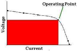
So no-load or no controller connected panel output is the highers voltage - ie, the y-axis "Voltage" value when Current = 0A.
Add a load and current increases. The panel voltage will be as read off the graph above - ie, the Voltage corresponding to the point on the curve with whatever current - aka the Operating point.
If that voltage is close to zero, then that panel is undersized for that load at that light intensity - maybe it's night time or cloudy?
Of course if the voltage is less than the battery terminal voltage, the panels won't be supplying any power. [ That's why MPPTs are used - apart from possibly including boost converters, they will sit at the maximum POWER point of the curve - which may be 17V for that light power and panel - and buck convert to 14.4V charging or a float of 13.4V at the battery terminals (else MPPT output). ]
BTW - That VI curve is similar across many power sources and circuits - eg, batteries, zenor regulators, alternators.
TV-wise I'd buy neither since neither are FULL HD. (Even my 23" PC monitor is FULL HD if not better.)
But otherwise - all things being equal, the unit with 12V connection especially since it comes with a cig-socket interface hence - unless that interface cord includes a regulator converter - meaning that its 12V DC input is indeed automotive 12V - eg up to 15V or 16V and lower than 12V without damage.
The AC-only version requires an inverter (DC-AC) which adds cost and inefficiency (probably ~30% of the load), and usually quite a high standby current (often 10W or more).
And similarly, an equivalent (automotive) DC DVD.
Tho I no longer have to carry an inverter (and a spare) to run my stuff because I have gradually sourced dc versions or supplies (cheaply!), I still carry a small inverter (but no spare) as a fallback in case of dc adapter failures.
AC/DC options are great for terrestrial travelers. (And for some, AC-DC is a good band, but I'll limit my pun/joke to that...)
FYI - for some reason many think that (modern) dc dc converters have no AC and hence no electrical noise. Except for linear down converters, AC is involved in all dc dc conversion.
In fact dc-ac inverters should be "quieter" than dc-dc converters because inverters are only dc-ac whereas (non-linear) dc-dc converters are dc-ac-dc. But their design means that the inverter AC output usually causes the noise.
However, some dc-dc converters are known to be far noisier than almost any inverter - they can cause havoc to FM & TV and even GPS reception, and effect car audio, PCs, etc. (Dare I mention the M4 car PC supply?)
[ More importantly to me is NOT having tunnel vision. IMO so many have arguments with me because they don't see past their rut nor understand other interactions - aka the big picture - and they confuse situations & theory, The Red dude is a classic as was a recent deleted thread hereon. In person verbals or classrooms rarely have such problems because if real time interaction & adaptation. (And for some reason, people seem to avoid getting personal in person. I often wonder if they would if remote writing?) ]
Anyhow, it was not my last reply that was epic I thought it was.
Ok, I think the voltage drop with/without controller from the solar panels is easy - it's a typical "non ideal" power source. Jump to the diagram/graph below, or read the following if needed.
The ideal power source (battery, generator, solar panel, partner) has no resistance, ie a "zero-impedance power supply".
That means no matter what load is placed on them, they retain constant voltage and no voltage says (brown outs etc).
In the case of partners, it means that despite them gibing you the support or strength for real life, they exhibit zero resistance to your directions - ie, scratch back, find keys, do shopping, empty garbage, earn income.
Alas it's not an ideal world. A battery is (modeled as) an ideal battery (eg always 12.67V with infinite current etc) and a series resistance (often referred to as ESR = Equivalent Series Resistance which increases in resistance as the battery discharges).
Hence a fully charged 12.7V battery with ESR of 10mR supplying 100A with have a terminal voltage of 12.7 - (100A x 0.01 Ohm) = 12.7 - 1.0V = 11.7V.
(FYI - The same battery if ~10% discharged (ie, 12.5V) might have ESR = 15mR hence 12.5V - (100A x 15mR) = 12.5 - 1.5V - 11.0V.)
For solar panels, look at www.reuk.co.uk's Measuring the Power of A Solar Panel for the fllowing:
So no-load or no controller connected panel output is the highers voltage - ie, the y-axis "Voltage" value when Current = 0A.
Add a load and current increases. The panel voltage will be as read off the graph above - ie, the Voltage corresponding to the point on the curve with whatever current - aka the Operating point.
If that voltage is close to zero, then that panel is undersized for that load at that light intensity - maybe it's night time or cloudy?
Of course if the voltage is less than the battery terminal voltage, the panels won't be supplying any power. [ That's why MPPTs are used - apart from possibly including boost converters, they will sit at the maximum POWER point of the curve - which may be 17V for that light power and panel - and buck convert to 14.4V charging or a float of 13.4V at the battery terminals (else MPPT output). ]
BTW - That VI curve is similar across many power sources and circuits - eg, batteries, zenor regulators, alternators.
TV-wise I'd buy neither since neither are FULL HD. (Even my 23" PC monitor is FULL HD if not better.)
But otherwise - all things being equal, the unit with 12V connection especially since it comes with a cig-socket interface hence - unless that interface cord includes a regulator converter - meaning that its 12V DC input is indeed automotive 12V - eg up to 15V or 16V and lower than 12V without damage.
The AC-only version requires an inverter (DC-AC) which adds cost and inefficiency (probably ~30% of the load), and usually quite a high standby current (often 10W or more).
And similarly, an equivalent (automotive) DC DVD.
Tho I no longer have to carry an inverter (and a spare) to run my stuff because I have gradually sourced dc versions or supplies (cheaply!), I still carry a small inverter (but no spare) as a fallback in case of dc adapter failures.
AC/DC options are great for terrestrial travelers. (And for some, AC-DC is a good band, but I'll limit my pun/joke to that...)
FYI - for some reason many think that (modern) dc dc converters have no AC and hence no electrical noise. Except for linear down converters, AC is involved in all dc dc conversion.
In fact dc-ac inverters should be "quieter" than dc-dc converters because inverters are only dc-ac whereas (non-linear) dc-dc converters are dc-ac-dc. But their design means that the inverter AC output usually causes the noise.
However, some dc-dc converters are known to be far noisier than almost any inverter - they can cause havoc to FM & TV and even GPS reception, and effect car audio, PCs, etc. (Dare I mention the M4 car PC supply?)