I have a 2006 vulcan 900 and I have some white led lights that light up the bike at night, they are on a constant switch so they can be on whenever I want. The question I have is I want to shut the lights off when I put my turn signals on so you can see the yellow led lights for the turn signals underneath but every wire I have tested and found it is always a toggle from ground to 12v or the other way around. Where could i find a wire that just goes from ground to 12v or 12v to ground so I can activate a relay and shut off the white lights?
The wires you are testing are probably not toggling from 12 to ground, or vice versa. You are simply getting a ground type reading via the light bulbs.
but if I hook up a relay to those wires will the relay stay engaged or with it go on and off?
You need a circuit that senses the +12V
flashes to the indicators and stays active during the off pulses.
IE - charge a capacitor though a diode...
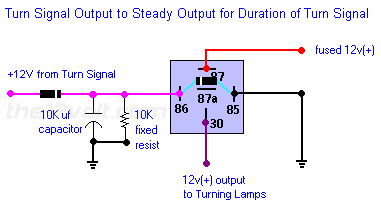
... as from
top of page Pulsed to Steady Output...
BUT without the 10k resistor (IMO not needed - nor is the diode across 85 & 86)...
AND connect the LED(s) to 87a instead of 87.
The NC (normally closed) relay contacts 30 & 87a can be either side of the LED(s) - ie, +12V supply or GND side. EG: +12V -> 87a -> 30 -> LED+ ; LED- -> GND.
The +12V pulses to 86 energise the relay (hence breaking 30-87a) and charge the capacitor.
The capacitor discharges via the relay coil. (The series diode from the flasher prevents discharging via the flasher bulbs.)
The relay hold up time is approximately RC where R is the resistance of the relay coil (Ohms) and C is the capacitance (Farads).
You want an approx 1 second delay, hence RC = 1.
You need one circuit per side unless you want all white LEDs off whichever side is flashing (in which case use a diode from EACH flasher side to the cap & relay).
Shouldn't this simple idea work, use 2 x 1N5404 diodes:-
indies.bmp-------------
Amateurs assume, don't test and have problems; pros test first. I am not a free install service.
Read the installation manual, do a search here or online for your vehicle wiring before posting.
That only operates whilst lit during flashing - it's the old "how to keep off whilst flashers are off" problem (ie - a time delay to hold between flashes is needed).
It will work if it's a +12V (or GND) "constant" signal that actuates the flasher can as with dual-purpose flasher lamp circuits - ie, combined flashers and brake or reverse lights.
But most flasher switches are after the flasher can - ie, IGN +12V to the can, then the flasher switch switches to the left else right lamps (or both for hazard flashers).
FYI - I've decided to use a PIC for my flasher lamp logic - whether combined flasher/reverse, or side flasher/clearance lamps (and maybe front flasher/running lamps). Hence no RC-decay relay chatter problems, and I can use PWM for bright-flasher (else off) or dim-clearance for the sides or front.