12v light flasher
Printed From: the12volt.com
Forum Name: General Discussion
Forum Discription: General Mobile Electronics Questions and Answers
URL: https://www.the12volt.com/installbay/forum_posts.asp?tid=132558
Printed Date: May 13, 2026 at 12:17 AM
Topic: 12v light flasher
Posted By: jasoncw27
Subject: 12v light flasher
Date Posted: November 02, 2012 at 11:04 PM
I am trying to wire up flashing lights for 2 RR Xing signs I built for my father in law's RR retirement. I thought this would be pretty easy, but it is proving to be too difficult for my electronic brain.
I tried wiring in a standard turn signal flasher, and use a SPDT relay to flash the 2 sides of the lights. This is not working. My guess is I don't have the right resistance in the circuit for the flasher to work.
When I have it wired like the attached diagram (sorry for the bad sketch), the lights all come on, but they do not flash. I wired in a resistor (the lowest I have is 330 Ohms), and the lights do not even come on. I assume this is because there is too much resistance.
Then I tried wiring in a 3157 bulb in series. On the high resistance side of the bulb, when the circuit is connected, the bulb buzzes, but it lights up; however, the RR sign lights do not light up. On the low resistance side, all bulbs light up (4 RR lights and the 3157), but they do not flash.
Can someone offer me suggestions? I tried to find a solid state flasher in my area to no avail. I need this done before 4PM EST Saturday (tomorrow), so I cannot order any parts.
Thanks for any help!
Jason 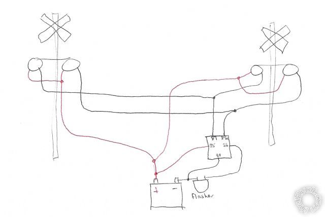
Replies:
Posted By: jasoncw27
Date Posted: November 02, 2012 at 11:56 PM
I am guessing I wired the relay wrong. I bypassed the relay, took the 3157 bulb out of the circuit, and they flash now. However, they are not alternating, of course. Can someone tell me where I went wrong in the relay wiring? I would really like to get these lights flashing alternately, like the real signs.
Thanks!
Jason
Posted By: lurch228
Date Posted: November 03, 2012 at 12:55 AM
The flasher needs to send power the the 86,87 on the relay. When the flasher is open the power flows to 87a until the flasher ribbon cools off and closes putting power back to the relay. If it still doesn't work then you need to wire the flasher and relay on the positive side. I have never tried wiring a flasher on the negitive side but it may work. So with your setup the flasher needs to be disconnected from the battery and connected between the left lights ground and the relay 87, 87 to 86, 30 to battery (-), 87a to right lights ground, 85 to battery (+). [FYI accepted standard for relays is 85 (-), 86 (+), But they can be reversed if need be.]
Posted By: itsyuk
Date Posted: November 03, 2012 at 2:16 PM
dont change your wiring, your wiring is correct. you just ned to get an electronic flasher. a bi-metal flasher like you are using wont get triggered by the draw of the relay coil alone.
the flasher i just tried before i typed this response was
https://www./itm/CEC-EF-32-ELECTRONIC-TRUCK-FLASHER-2-TERM-12V-12-LAMP-/370482450659?pt=Motors_Car_Truck_Parts_Accessories&hash=item56427990e3&vxp=mtr
and it worked perfect.
if you have trouble finding one, shop the nearest truckstop. ------------- yuk
quiet rural missouri, near KC.
If your system moves you physically and not emotionally, you have wasted your money.
Posted By: itsyuk
Date Posted: November 03, 2012 at 2:19 PM
BTW it has markings for which post gets X(12v) and which gets L(load). ------------- yuk
quiet rural missouri, near KC.
If your system moves you physically and not emotionally, you have wasted your money.
Posted By: lurch228
Date Posted: November 03, 2012 at 2:32 PM
Changing the wiring will put a load on the flasher that it needs to work. How do you think they did it before electronic flashers exisited. What he has will work! The way he has it in the diagram won't trigger thats why it needed to be moved to the load side with the lights.
Posted By: itsyuk
Date Posted: November 03, 2012 at 2:35 PM
i dont think so.
the light wont steadily alternate like at a railroad crossing ------------- yuk
quiet rural missouri, near KC.
If your system moves you physically and not emotionally, you have wasted your money.
Posted By: lurch228
Date Posted: November 03, 2012 at 5:02 PM
If the flasher is conducting current and the output is going to the coil 86 and the 87(Normally Open). It will energize and flow to battery through 87, when flasher opens the coil de-energizes and the other lights have flow on 87a(Normally Closed) until the flasher ribbon cools and closes and the cycle repeats. He has to seperate ground circuits and one positive. I would have done it with two positive circuits and one ground, but the priciple is the same. It's direct current not alternating current. If he follows the accepted standard relay wiring and wires 85 (-), 86,87 to load from flasher, 87a to other light circuit. It will alternate at the rate of the flasher opening and closing. Apparently you don't understand all the wiring configurations for relays and how they work.
Posted By: itsyuk
Date Posted: November 03, 2012 at 5:19 PM
dont try to insult me. i know what im talking about.
using his schematic and my flasher..
i mocked one of these up in my garage about 30 minutes ago using some old taillight sockets i had laying around and 1157 bulbs.
using the turn signal filiment wire and the ground from each socket not only did it work. it didnt even care which way the poarity was on the 85 and 86 terminals.
then i reversed the wires on the flasher and swapped the polarity on the battery and it STILL worked perfect. then i swapped the 85 and 86 wires around and it STILL FREAKIN worked..... tell me again what i dont under stand.(?) LOL
now.... please build it your way and tell us your results. ------------- yuk
quiet rural missouri, near KC.
If your system moves you physically and not emotionally, you have wasted your money.
Posted By: lurch228
Date Posted: November 03, 2012 at 5:33 PM
That doesn't mean that just because it works you way, dosen't mean it won't work with what he's got if wired correctly so get off you high horse. And you insult your self by believing that your way is the only way. I never said your way wouldn't work! But with what he has it will work if wired correctly! I maybe new to this forum but have been doing this for 25 years so think what you want. And let him figure the rest out for himself he has more than enuff information to get it done.
Posted By: itsyuk
Date Posted: November 03, 2012 at 11:04 PM
i took your current diagram with a regular car flasher and simply moved the wire from 87 and added it to the 86 terminal along with the other wire.
the system worked but flashed at a rate almost double of what my previous set up did.
flashed much like a car when a signal bulb is burned out on one end of the car.
probably still good enough to have at the party. ------------- yuk
quiet rural missouri, near KC.
If your system moves you physically and not emotionally, you have wasted your money.
Posted By: lurch228
Date Posted: November 03, 2012 at 11:39 PM
His diagram has the bulbs wired in parallel not series which halves the resistence. The less resistence ie less bulbs in series the faster the flash rate. To slow it down more just wire the bulbs in series or add resistors to acvheive the desired flash rate. Trial and error to find the right resistor value. Once again the electronic flasher dosen't rely on the total resistence of the circuit, it uses a set rate no matter the load, which is why they work so well for led blinker lights.
Posted By: itsyuk
Date Posted: November 03, 2012 at 11:47 PM
the paralleled bulbs should have blinked a normal rate ... like they are paralleld in a car. i wonder if the flasher i used might be weak. it was an old one layin in my garage.
more heat opens the flasher longer... less heat from a lighter load closes flasher early from lack of heat. ------------- yuk
quiet rural missouri, near KC.
If your system moves you physically and not emotionally, you have wasted your money.
Posted By: lurch228
Date Posted: November 04, 2012 at 1:08 AM
Flashers do get faster as they age so that could be your case. His diagram is only feeding 2 bulbs at a time the flasher in a car usually has 3 or 4 bulbs on a left or right circuit. Some high end cars have more than 4 and they usually alternate to reduce the resistence on the circuit. All the GM that I have owned had 2 1157 in each rear, and 1 1157, 194 in the front. Plus the gauge and length of the wire also effects the resistence.
Posted By: oldspark
Date Posted: November 04, 2012 at 3:46 AM
Lurch, you are saying several incorrect things, eg:
lurch228 wrote:
His diagram has the bulbs wired in parallel not series which halves the resistence. The less resistence ie less bulbs in series the faster the flash rate.
Bulbs in parallel lessens (halves) the resistance is correct. That usually increases the flash rate for bi-metal flashers - ie, more current.
There are no bulbs in series.
And the "blown bulb" fast flash rate is only when there is less than two "normal" bulbs, ie, one of the two 21W-27W has blown. (That means a higher resistance.)
lurch228 wrote:
His diagram is only feeding 2 bulbs at a time the flasher in a car usually has 3 or 4 bulbs on a left or right circuit.
Yes, but the extra bulbs are usually less than the normal main ~21W front and rear flasher bulbs - ie, they are usually 2W-3W bulbs for sides and dash indicators.
lurch228 wrote:
Changing the wiring will put a load on the flasher that it needs to work.
As above.
A very high load may mean very fast flashing rate in bi-metal flashers (higher current, faster hating), but many bi-metals these days handle two to six high-power bulbs - eg, of ~21W. (In old days hazard cans were separate to left-right only flasher cans.)
But a relay coil adds insignificant load. A LED adds even less.
Hence it's ok to add relay coils or LEDs in parallel with existing bulbs. It is generally not okay to have mere coils or LEDs if there is insufficient loading (ie, 2x21W bulbs or a ~4R 50W resistor etc).
And rarely is a flasher can connected to 30 & 87 or 87a etc.
They are usually connected to the coil (86/85) so that extra lights can be driven without overloading the flasher can. Of course, that relay de-energises when the can is off, hence you can't just connect parker power to 87a - the coil needs a delay-off circuit to ride thru the can off times.
If I skimmed thru the previous posts too quick and have thus misunderstood, I apologise.
But be careful, all too often I have misapplied flasher workings even though I've done enough dual-function bulbs involving flashers to know better!
Posted By: lurch228
Date Posted: November 04, 2012 at 4:32 AM
oldspark wrote:
Lurch, you are saying several incorrect things, eg:
lurch228 wrote:
His diagram has the bulbs wired in parallel not series which halves the resistence. The less resistence ie less bulbs in series the faster the flash rate.
Bulbs in parallel lessens (halves) the resistance is correct. That usually increases the flash rate for bi-metal flashers - ie, more current.
There are no bulbs in series.
And the "blown bulb" fast flash rate is only when there is less than two "normal" bulbs, ie, one of the two 21W-27W has blown. (That means a higher resistance.)
The series part was meant to increase resistence which in turn = less current slower flash, correct?
lurch228 wrote:
His diagram is only feeding 2 bulbs at a time the flasher in a car usually has 3 or 4 bulbs on a left or right circuit.
Yes, but the extra bulbs are usually less than the normal main ~21W front and rear flasher bulbs - ie, they are usually 2W-3W bulbs for sides and dash indicators.
lurch228 wrote:
Changing the wiring will put a load on the flasher that it needs to work.
This was meant to say that the way he has it wired would not allow it to flash due to the fact that the flasher was not passing current through to the bulbs only to the relay coil which cant pass enuff current to make the flasher work.
As above.
A very high load may mean very fast flashing rate in bi-metal flashers (higher current, faster hating), but many bi-metals these days handle two to six high-power bulbs - eg, of ~21W. (In old days hazard cans were separate to left-right only flasher cans.)
But a relay coil adds insignificant load. A LED adds even less.
Hence it's ok to add relay coils or LEDs in parallel with existing bulbs. It is generally not okay to have mere coils or LEDs if there is insufficient loading (ie, 2x21W bulbs or a ~4R 50W resistor etc).
And rarely is a flasher can connected to 30 & 87 or 87a etc.
They are usually connected to the coil (86/85) so that extra lights can be driven without overloading the flasher can. Of course, that relay de-energises when the can is off, hence you can't just connect parker power to 87a - the coil needs a delay-off circuit to ride thru the can off times.
What I wrote would only power the coil and one side of the lights with the flasher, and the other side direct to battery through the relay when not energized.
If I skimmed thru the previous posts too quick and have thus misunderstood, I apologise.
But be careful, all too often I have misapplied flasher workings even though I've done enough dual-function bulbs involving flashers to know better!
I did make a mistake with the wiring that I posted that [85(+)] should have been 85(-). But I PM'd him about the mistake since I couldn't edit the post. I don't do alot of flashers but I try to help and learn along the way.
If there is anything else please post back.
Posted By: oldspark
Date Posted: November 04, 2012 at 5:48 AM
Ooops - sorry Lurch - my bad!!.
The orig diagram shows the can flashing ONLY the relay coil. (And as Lurch wrote, that will cause problems or non-operation on ANY type of flasher can, though some electronic flashers can be modified, but then IMO make your own with a 555 timer etc and a relay instead.)
I thought the original bulbs were still across the can, and the relay coil merely added (across the can - ie, across the bulbs).
Maybe the whole of my reply is invalid because a skimmed the rest as fast as I obviously skimmed the diagram! 
And don't take this the wrong way - I'm not overly keen on rereading this thread in detail etc.
I just saw the main intent and offered a simple solution IF out-of-phase flashing is acceptable, AND the "new" (or dual-function) bulb's ground can be re-routed.
I've written enough times elsewhere pointing out that these sorts of flasher circuits rarely involve a "simple" relay interface if the circuit needs to ride-thru the flasher's intermediate off pulses.
Sometimes a DPDT solution can be used (actually 1 x SPDT & 1 x SPST) but that requires the can to be switched to each side's bulbs thru the relay contacts, and hence flasher-can rewiring (to after the flasher switch - the switch instead switches the relay coils).
Otherwise it involves a PIC or other timer circuit, or a capacitive "keep energised" delay for the single relay (SPDT).
{I like a PIC that controls the bulb direct, hence can add PWM dimming for use as a dimmer running/clearance light etc - though that's usually when LEDs are involved.)
Sorry Lurch. I should have known better! And sorry to if I came across rudely or viciously etc.
[No need to reply with a "that's ok" or cool etc. This site doesn't have grudge-bearing contributors (except perhaps me!), and it was totally MY BAD. Maybe I will reread in the morning - just to see if I was an r'sole! And if I find other good links...]
Posted By: lurch228
Date Posted: November 04, 2012 at 7:22 AM
oldspark Please look it over and see what you think.
How well will modifying the original diagram to this work?
Left lights(-) to flasher, flasher to the relay 87, 87 to 86, 30 to battery (-), right lights to 87a, 85 to battery(-)
Posted By: itsyuk
Date Posted: November 04, 2012 at 12:18 PM
but still, an elctronic flasher replacing the bi-metal flasher solves the whole problem.
and as a model railroader friend pointed reminded me. if you pop open the electronic flasher and replace the resister with a pot, you can adjust the flashrate. ------------- yuk
quiet rural missouri, near KC.
If your system moves you physically and not emotionally, you have wasted your money.
Posted By: lurch228
Date Posted: November 04, 2012 at 4:30 PM
itsyuk wrote:
but still, an elctronic flasher replacing the bi-metal flasher solves the whole problem.
and as a model railroader friend pointed reminded me. if you pop open the electronic flasher and replace the resister with a pot, you can adjust the flashrate.
That same pot will do basicly the same (like an adjustable resistor) in the curcuit with a bi-metal flasher if placed in the common wire ie positive in his diagram, with one difference the bi-metal will heat slower with less current but the cool off will not change much. Which if set to slow will flash uneven or possibly not at all.
|