the12volt.com spacer
icon

display board relay setup?


Post ReplyPost New Topic
< Prev Topic Next Topic >
carraudio 
Member - Posts: 26
Member spacespace
Joined: September 19, 2004
Location: Nebraska, United States
Posted: December 29, 2011 at 2:48 AM / IP Logged  
I just started working at a small shop here in Nebraska and we don't have a switchable display and I want to make one. I did search and found THIS. When I tried to make the latched relay part to see if it worked I could get it to go from 5 down and it would release the previous relay but if I start at 1 or just try to go up the chain to the next relay it won't release the previous relay. I can see why it is doing what it is doing. It will release the higher relay because when the lower is energized the delay in the switching breaks the 12 volts but it won't do it going the other way. How do I fix this?
carraudio 
Member - Posts: 26
Member spacespace
Joined: September 19, 2004
Location: Nebraska, United States
Posted: December 30, 2011 at 8:09 AM / IP Logged  
I have it figured out. I will have to use HWW diagram here that uses two relays and just diode iso all the unlatch triggers. I will keep you posted with pics once this is started.
If anyone has any input that I may need to know feel free to post it.
carraudio 
Member - Posts: 26
Member spacespace
Joined: September 19, 2004
Location: Nebraska, United States
Posted: January 05, 2012 at 9:12 PM / IP Logged  
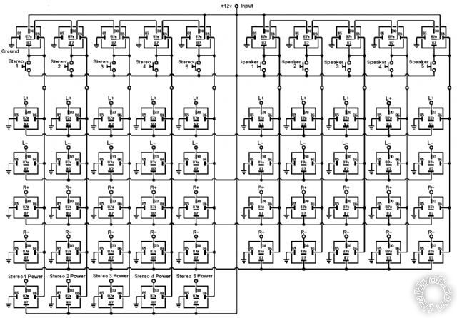
Things for this have started to come in...
150 relays...
display board relay setup? - Last Post -- posted image.
200 diodes ...
display board relay setup? - Last Post -- posted image.
500 connectors...
display board relay setup? - Last Post -- posted image.
I can't wait to get started with this.
oldspark 
Gold - Posts: 4,913
Gold spacespace
Joined: November 03, 2008
Location: Australia
Posted: January 06, 2012 at 1:48 AM / IP Logged  
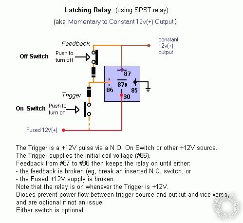
With 2 switches (an NO and an NC), why not the circuit below where the "constant +12V output" is +12V after pressing on and if off after removing power else pressing the off button. One or both diodes may be optional.
display board relay setup? - Last Post -- posted image.
(eg, as used here.)
hotwaterwizard 
Silver - Posts: 1,350
Silver spacespace
Joined: December 11, 2003
Location: California, United States
Posted: January 09, 2012 at 9:12 PM / IP Logged  
display board relay setup? - Last Post -- posted image. 
John DeRosa (Hotwaterwizard)
Stockton California
When in doubt, try it out !
hotwaterwizard 
Silver - Posts: 1,350
Silver spacespace
Joined: December 11, 2003
Location: California, United States
Posted: January 11, 2012 at 9:41 PM / IP Logged  

Okay Here is the best Fix I could figure out for you.

Add an extra button and relay to reset off.

Then select which one you want.

display board relay setup? - Last Post -- posted image.

John DeRosa (Hotwaterwizard)
Stockton California
When in doubt, try it out !
carraudio 
Member - Posts: 26
Member spacespace
Joined: September 19, 2004
Location: Nebraska, United States
Posted: January 25, 2012 at 7:57 AM / IP Logged  
If did it that way I wouldn't want to make the off one latched. I think I'm just going to use this relay setup
display board relay setup? - Last Post -- posted image.
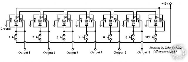
it will take a bunch of diodes to do the unlatching but it will work like I want it to.
carraudio 
Member - Posts: 26
Member spacespace
Joined: September 19, 2004
Location: Nebraska, United States
Posted: February 22, 2012 at 9:23 PM / IP Logged  
So we have been slammed at work for the past few weeks. It has been nice but no chance to work on my display. Here is what i have so far...
display board relay setup? - Last Post -- posted image.
If you look to the left you can see my latched relays.
display board relay setup? - Last Post -- posted image.
hotwaterwizard 
Silver - Posts: 1,350
Silver spacespace
Joined: December 11, 2003
Location: California, United States
Posted: March 03, 2012 at 6:21 PM / IP Logged  

Looks great !

The problem is that my diagram is a concept.

 I never built the circuit.

You went that extra step.

 Please let me know how it works out.

John DeRosa (Hotwaterwizard)
Stockton California
When in doubt, try it out !
carraudio 
Member - Posts: 26
Member spacespace
Joined: September 19, 2004
Location: Nebraska, United States
Posted: March 03, 2012 at 7:32 PM / IP Logged  
It will work great once I get time to work on it. I'm trying to find a cheap way to hold my diodes for the switches. It is either 32 single row barrier strips or I might do something with mdf. The shop is just so small we don't have a wood shop.

Sorry, you can NOT post a reply.
This topic is closed.

  Printable version Printable version Post ReplyPost New Topic
You cannot post new topics in this forum
You cannot reply to topics in this forum
You cannot delete your posts in this forum
You cannot edit your posts in this forum
You cannot create polls in this forum
You cannot vote in polls in this forum

  •  
Search the12volt.com
Follow the12volt.com Follow the12volt.com on Facebook
Thursday, April 25, 2024 • Copyright © 1999-2024 the12volt.com, All Rights Reserved Privacy Policy & Use of Cookies
Disclaimer: *All information on this site ( the12volt.com ) is provided "as is" without any warranty of any kind, either expressed or implied, including but not limited to fitness for a particular use. Any user assumes the entire risk as to the accuracy and use of this information. Please verify all wire colors and diagrams before applying any information.

Secured by Sectigo
the12volt.com spacer
Support the12volt.com
Top
the12volt.com spacer