the12volt.com spacer
icon

2006 Dodge Ram 1500 Remote Start Pictorial


Post ReplyPost New Topic
< Prev Topic Next Topic >
kreg357 
Platinum - Posts: 7,783
Platinum spaceThis member has made a donation to the12volt.com. Click here for more info.spaceThis member has been recognized as an authority in Electrical Theory. Click here for more info.spaceThis member has been recognized as an authority in Mobile Security and Convenience. Click here for more info.spacespace
Joined: January 30, 2009
Location: Pennsylvania, United States
Posted: January 06, 2012 at 8:11 PM / IP Logged  

This pictorial will be a specific remote start with keyless entry for a 2006 Dodge Ram 1500 Quad Cab geared towards the DIYer.  Yes!  She's got a HEMI!

The “specific” aspect will be the use of an iDatalink bypass module and listing only the vehicle wires needed to effect the install.  This truck has a transponder  based ignition immobilizer, a MUX Start/Accessory/Keysense system, a single wire door lock system and a MUX based Headlight/Parking Light system.  As such, it represents several challenges to the installer.  Using the iDatalink bypass module allows the installer to make just 11 connections to the truck ( including the Hood Safety ).

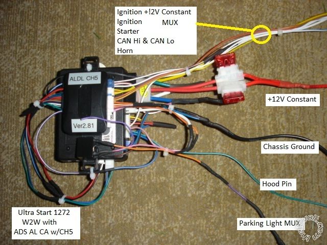
Shown below is a bench prepped remote start unit with the iDatalink bypass module.  All wire connections are done in the W2W fashion exactly following the diagram provided by iDatalink.  W2W will allow the bypass to work with any ( quality ) remote start unit.

2006 Dodge Ram 1500 Remote Start Pictorial -- posted image.

Disassembly :  Remove two Phillips screws at the bottom corners of the lower dash panel.  Pull the panel at the top, straight away from the dash.  There are three plastic clips on the left side and one on the right. This will expose the metal plate shown below :

2006 Dodge Ram 1500 Remote Start Pictorial -- posted image.

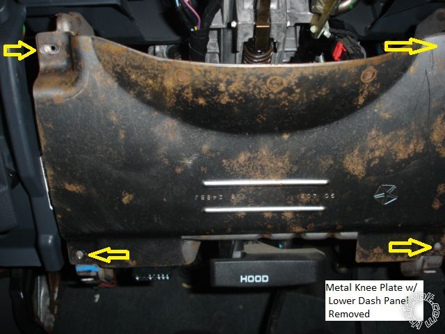
Remove the four Phillips screws marked, lift the plate up slightly and remove.

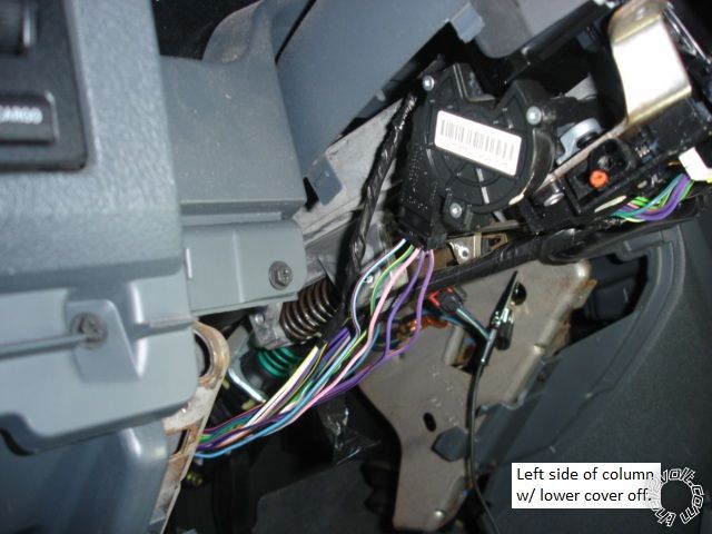
Remove the lower steering column cover using a Torx T-20 driver.  First remove the Tilt Wheel knob ( one screw ).  Next, remove three Torx screws at the underside of  the lower cover.  Squeeze the steering cover in at both sides along the seam to separate the two halves and remove the lower section.

Removing the side dash panel will allow easy access to the back of the Headlight switch and for antenna cable installation.  Gently pry it open with non-marring tools.  There are four plastic retaining clips.

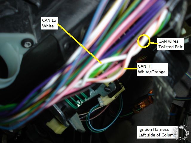
Along the left side of the steering column is the ignition harness.  This bundle of wires contains the Horn, CAN Bus wires, and the four ignition wires.

2006 Dodge Ram 1500 Remote Start Pictorial -- posted image.

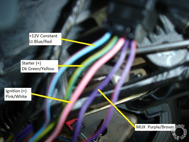
Here is a picture of the Ignition wires.  ( Closer and out of focus, sorry. )

2006 Dodge Ram 1500 Remote Start Pictorial -- posted image.

The CAN wire, also out of focus, found in the same harness.

2006 Dodge Ram 1500 Remote Start Pictorial -- posted image.

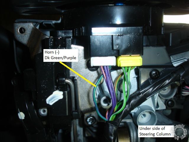
Here is picture of the Horn (-) wire at the steering wheel connector.  It, too, can be found in the same column harness

.

2006 Dodge Ram 1500 Remote Start Pictorial -- posted image. 

Here is a picture of the Headlight Switch connector.  There are two WHITE/ Lt Green wires in this connector.  The correct MUX wire is marked.

2006 Dodge Ram 1500 Remote Start Pictorial -- posted image.

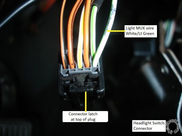
This was the only wire not directly controlled by the bypass module.  All reference sources listed this connection as needing a relay with the wire going to ground thru a 1130 Ohm resistor.  My fabricated resistor measured 1137 ohms and turned on the Headlights.  Ended up getting the Parking Lights on at 1850 ohms and soldered in a 2,000 ohm resistor that reliably flashed the Parking Lights.  A 5K ohm multi-turn potentiometer would make finding the correct resistance value easier.

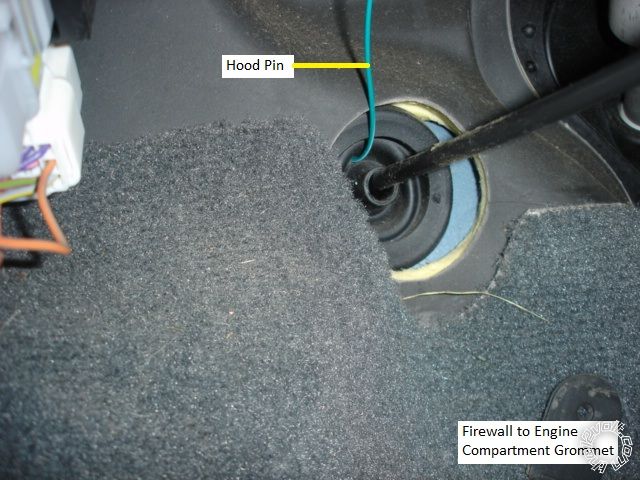
Here is a picture of a convenient grommet for the Hood Safety wire pass-thru.

2006 Dodge Ram 1500 Remote Start Pictorial -- posted image.

Not shown are the Chassis Ground and main 12V Constant connections to the remote starter.  There are two factory ground bolts at either side of the

steering column channel under the dash.  While the current draw of the remote starter is low, a direct connection to the battery is recommended.

The iDatalink bypass module handles the locks, alarms and bypass thru CAN Bus data.  It supplies the remote starter with the Brake signal and a

Tach signal.  It also supplies a Door Status signal for an alarm system.  Due to the “data” type nature of many of the vehicle wires, all connections
should be securely soldered and well insulated.

There is plenty of room under the dash for module placement.  While I used an ADS AL CA bypass module flashed with the ADS AL(DL) CH5 firmware, DIYers will find it easier to obtain the pre-loaded Solo Series ADS-ALSL CH or ADS-DLSL CA2.   Please note that there are many ways and methods to install a remote start w/keyless into this truck.  The description above is fast, fairly easy, very reliable, does not require two working keys for module programming and costs about $100.

Soldering is fun!
howie ll 
Pot Metal - Posts: 16,466
Pot Metal spacespace
Joined: January 09, 2007
Location: United Kingdom
Posted: January 09, 2012 at 1:24 AM / IP Logged  
Nice one Kreg, I noticed the red sleeving on the constant, someone else as anal as me?
Lot of rust on that knee panel for an 06?
kreg357 
Platinum - Posts: 7,783
Platinum spaceThis member has made a donation to the12volt.com. Click here for more info.spaceThis member has been recognized as an authority in Electrical Theory. Click here for more info.spaceThis member has been recognized as an authority in Mobile Security and Convenience. Click here for more info.spacespace
Joined: January 30, 2009
Location: Pennsylvania, United States
Posted: January 09, 2012 at 5:59 AM / IP Logged  

Yes, learning from the best.  Quality in equals quality out.  Purchased a roll of red heat shrink tube and use it on the 12V constant wires.  As another post questioned, you can combine and fuse down ( 30A to 10A ) the R/S power inputs if the install circumstances allow.  

If you look really closely, you can see a quenching diode across the coil leads on the parking light MUX relay.  2006 Dodge Ram 1500 Remote Start Pictorial -- posted image.  (  Top picture, small black relay below the bypass module. )

See that rust on un-finished metal often, even on "high and dry" areas.  Imagine you saw plenty of that in a warm, moist climate like Florida?

Soldering is fun!
howie ll 
Pot Metal - Posts: 16,466
Pot Metal spacespace
Joined: January 09, 2007
Location: United Kingdom
Posted: January 09, 2012 at 6:17 AM / IP Logged  
Ref. the relay coil, yes but neater than my efforts, probably why I use 30mm (11/4") sleeving! It answer's why I wondered about brown going to green, but then like me you pre-make your relays, DEI* 8166 at $3.30 trade? Do me a favour Mouser or Farnell or the UK equivalent about £1.60 DIY, inc. diode, cable which would be lying around any way and sleeving, about $1!
Florida (because of the heat?), never seemed to suffer, Seattle area, here or the worst I've seen, Belgium on the English Channel coast, coldish, damp, and all that North Sea salt.
The big laugh for me is Chrysler + Fiat, do you use "COLANDER" as a kitchen utensil? Yes you know where this is going.

Sorry, you can NOT post a reply.
This topic is closed.

  Printable version Printable version Post ReplyPost New Topic
You cannot post new topics in this forum
You cannot reply to topics in this forum
You cannot delete your posts in this forum
You cannot edit your posts in this forum
You cannot create polls in this forum
You cannot vote in polls in this forum

  •  
Search the12volt.com
Follow the12volt.com Follow the12volt.com on Facebook
Thursday, April 18, 2024 • Copyright © 1999-2024 the12volt.com, All Rights Reserved Privacy Policy & Use of Cookies
Disclaimer: *All information on this site ( the12volt.com ) is provided "as is" without any warranty of any kind, either expressed or implied, including but not limited to fitness for a particular use. Any user assumes the entire risk as to the accuracy and use of this information. Please verify all wire colors and diagrams before applying any information.

Secured by Sectigo
the12volt.com spacer
Support the12volt.com
Top
the12volt.com spacer