the12volt.com spacer
icon

2007 toyota highlander, remote start


Post ReplyPost New Topic
< Prev Topic Next Topic >
aztec06 
Member - Posts: 10
Member spacespace
Joined: January 07, 2012
Location: Illinois, United States
Posted: January 14, 2012 at 5:08 PM / IP Logged  
Okay were going to start from the beginning... To test the alarm unlock & lock outputs how would I test for them correctly??? anyone!
shortcircuit161 
Silver - Posts: 556
Silver spaceThis member has made a donation to the12volt.com. Click here for more info.spacespace
Joined: August 29, 2010
Location: United States
Posted: January 14, 2012 at 9:29 PM / IP Logged  
Ok to start from the very beginning with the lock/unlock setup
-Take your multimeter and find a 12v constant power feed (probably from the remote starter harness or ignition harness. Possibly at the fuse box)
-Plug or clip your positive test wire from your multimeter to this 12v constant connection.
-You will then use your negative test wire to test each of the lock and unlock wires from the Viper harness. The blue and green ones.
-First connect the negative test wire to the blue unlock wire and press unlock on the Viper remote. Your test meter should quickly show 12v and then 0v again.
-Then try the same test on the green lock wire while pressing the lock button on the Viper remote.
Once you've established that both wires are working correctly by sending ground pulses, you would check the connections made in the door.
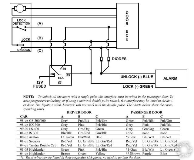
-First connect the blue unlock wire from the Viper system that's split into two wires with diodes (bands toward the blue unlock wire); one split to the Brown lock detection wire and the other to the Yellow unlock wire in the car.
-Test that first with the Viper remote to make sure you can unlock the doors.
-Then, connect the relay with
Pin 87 to one side of the Brown lock detection wire
Pin 30 to the other side of the lock detection wire
Pin 85 needs a wire providing 12v constant power (must have this setup for the relay to work)
Pin 86 - see below
-Then from the Green wire from the Viper system, (split into 2 wires), one end goes to Pin 86 of the relay and the other end goes to the Green lock wire in the car.
-Test that with the Viper remote to make sure you can lock the doors.
Here is a different image of the whole setup that may help.
2007 toyota highlander, remote start - Page 3 - Last Post -- posted image.
Mike M2 
Platinum - Posts: 2,652
Platinum spacespace
Joined: June 29, 2005
Location: United States
Posted: January 15, 2012 at 9:52 AM / IP Logged  

You can get power for the relay right at the drivers window switch. I think it is a thicker green wire, and this will be one less wire you need to run. A few years back one of my installers ran it thru the boot and it shorted out, cost us a thousand bucks to fix.

Mike M2
Tech Manager
CS Dealer Services
zerepdivad 
Silver - Posts: 605
Silver spaceThis member has made a donation to the12volt.com. Click here for more info.spacespace
Joined: July 03, 2006
Location: Wisconsin, United States
Posted: January 15, 2012 at 10:17 PM / IP Logged  
I just did one of these yesterday and got my locks in the passengers kick panel. But I imagine at this point you're a bit past that point.
A DMM is a beautiful thing.
MECP Advanced Installer Certified.
aztec06 
Member - Posts: 10
Member spacespace
Joined: January 07, 2012
Location: Illinois, United States
Posted: January 16, 2012 at 1:46 PM / IP Logged  
zerepdivad ... did you do it like the diagram displayed on top?? or did you do this a different way?    I am going to make the harness .... as above but for the pass. kick panel instead... what colors were used on the passenger side... did you used the harness coming from the BECU or the plug already going inside the Door panel?   
Thanks Alot guys for you guy's help... well the drivers side didnt work so I'll be doing this on the other side.. see how it goes... this same setup... Also I was given another method.. going direct with the lock output & unlock output from the remote.. using on the unlock output divide it with 2 diodes one on unlock & other on unlock detection then going direct with the lock. but Im not sure if thats going to work.... if the diagram on top doesnt work.. then if not I'll go and buy the xk01 module instead... I Cant believe im actually struggling with this.. i've done so many different mods on different cars and this one is getting to me...
zerepdivad 
Silver - Posts: 605
Silver spaceThis member has made a donation to the12volt.com. Click here for more info.spacespace
Joined: July 03, 2006
Location: Wisconsin, United States
Posted: January 20, 2012 at 7:42 PM / IP Logged  
14 pin plug grey and purple. straight negatie triggers. Test to verify as always.
I would hope by now you figured this out though.....
A DMM is a beautiful thing.
MECP Advanced Installer Certified.
Page of 3

Sorry, you can NOT post a reply.
This topic is closed.

  Printable version Printable version Post ReplyPost New Topic
You cannot post new topics in this forum
You cannot reply to topics in this forum
You cannot delete your posts in this forum
You cannot edit your posts in this forum
You cannot create polls in this forum
You cannot vote in polls in this forum

  •  
Search the12volt.com
Follow the12volt.com Follow the12volt.com on Facebook
Tuesday, April 23, 2024 • Copyright © 1999-2024 the12volt.com, All Rights Reserved Privacy Policy & Use of Cookies
Disclaimer: *All information on this site ( the12volt.com ) is provided "as is" without any warranty of any kind, either expressed or implied, including but not limited to fitness for a particular use. Any user assumes the entire risk as to the accuracy and use of this information. Please verify all wire colors and diagrams before applying any information.

Secured by Sectigo
the12volt.com spacer
Support the12volt.com
Top
the12volt.com spacer