the12volt.com spacer
icon

2012 Honda Pilot w/ Avital 4115L and iDatalink ADS-ALCA


Post ReplyPost New Topic
< Prev Topic Next Topic >
notaguest 
Member - Posts: 7
Member spacespace
Joined: October 22, 2018
Location: Pennsylvania, United States
Posted: October 22, 2018 at 11:00 AM / IP Logged Link to Post Post Reply Quote notaguest
Hi Guys,
I appreciate some guidance. Any help would be greatly appreciated. I have attempted my first Remote Starter installation in my car but I am having a couple of doubts and concerns. Here are some of my questions
- What firmware should I be using? ADS-AL(DL)-HA3 firmware or DBI-AL(DL)-HA3 firmware for the iDatalink bypass module? What is the difference between the two? I currently have the DBI firmware installed.
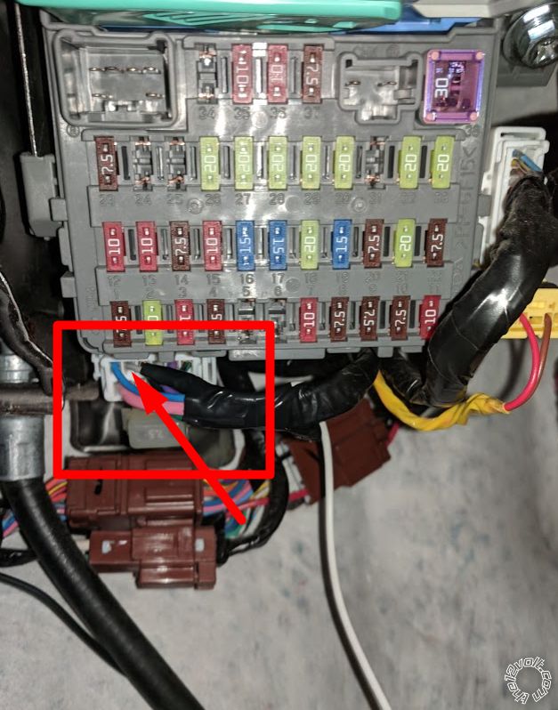
- In the main ignition of the vehicle I connected the following
DESCRIPTION      VEHICLE WIRES      REMOTE STARTER WIRES
12V (+) INPUT      White      2x Red
STARTER      Yellow      Purple
ACC      Red      Orange
IGNITION      Pink      Pink
NOT_IDENTIFIED      Orange      Not_Connected   <-- Not sure what this cable is but when I use the key to start the engine, the voltage drops while the STARTER is running and goes to 12V when the key is set to the "ignition" should i connect the pink/white cable from the RS? Some other forums call this the secondary ACC. Is this needed? what would require this connection to be enabled?
- My understanding is that the Bypass module should be able to get all the information from the CAN bus and control the majority of the vehicle behavior. I am having trouble getting the remote starter to trigger the horn or enable the parking lights or even get the status of the Park/Neutral switch.
So here are the other additional connections I made:
- For the bypass module, I connected the CANH, CANL, Key Data, and IGNITION keys just like the bypass instructions call out.
- Between the Remote Starter and the Bypass module i connected the D2D cable.
- For the remote starter, the I connected the ground and the heavy duty starter cables mentioned before.
Now when I tried running the starter, I could hear the RS click, but not start anything. Running the remote starter shutdown diagnostics, it said it was erroring out because it didn't have the parking/neutral ground connected. So as a test, I just grounded that cable and now the remote starter seems to be working. This makes me nervous because if all of the instructions don't mention the fact that that cable from the remote starter needs to be connected, I wonder what other cables need to be connected that I may be missing. Any of you know?
Any insight will be greatly appreciated.
silvercivicsir 
Copper - Posts: 402
Copper spacespace
Joined: November 21, 2003
Posted: October 22, 2018 at 4:54 PM / IP Logged Link to Post Post Reply Quote silvercivicsir
use the DBI-(DL-Ha-3) since you have a avital/viper unit. Ground the "thin blk/blkwhite wire",(this wire is only needed when you install in manual transmissions). make sure learn to learn the tach, and the Idata will not flash the park lights / do the horn . (those need to be hard wired).
notaguest 
Member - Posts: 7
Member spacespace
Joined: October 22, 2018
Location: Pennsylvania, United States
Posted: October 22, 2018 at 10:36 PM / IP Logged Link to Post Post Reply Quote notaguest
Great! Thank you so much. Now, If i was to hard wire the park lights, where should I go to? I've found many forums call out different locations. I ended up picking this site because I wanted the same notification lights used with the original FOB
to be used, but im a little afraid if its the correct one ore not.
Car Parking Lights Wire (+): Gray
Car Parking Lights Wire Location: At Under Dash Fuse Box
Any chance you may know? Here's an image of the wire i'm looking at tapping.
2012 Honda Pilot w/ Avital 4115L and iDatalink ADS-ALCA - Last Post -- posted image.
I tested it with a volt meter and when the locks are triggered from the orignal FOB, the wire goes to 12v. Do you happen to know if this is correct? or am I looking at something else?
Thank you for the help.
silvercivicsir 
Copper - Posts: 402
Copper spacespace
Joined: November 21, 2003
Posted: October 23, 2018 at 10:21 AM / IP Logged Link to Post Post Reply Quote silvercivicsir
test the wire again with the volt meter / test light.. (but this time try turning on the park lights. the test light / meter should show 12V when the lights are on). I usually find it easier to get the - wire at the switch. which says it's grey.
From what I can see, it says its a grey wire (+), but in a green plug 42 pin plug, pin 19
notaguest 
Member - Posts: 7
Member spacespace
Joined: October 22, 2018
Location: Pennsylvania, United States
Posted: October 24, 2018 at 8:13 AM / IP Logged Link to Post Post Reply Quote notaguest
Thank you for your help, I ran the the line at harness I pointed out in my previous message. Ran the test you suggested of turning on the parking lights and measuring the voltage and the line went to 12V. I am done with my installation. Once again, thank you for your help.
notaguest 
Member - Posts: 7
Member spacespace
Joined: October 22, 2018
Location: Pennsylvania, United States
Posted: October 30, 2018 at 8:59 AM / IP Logged Link to Post Post Reply Quote notaguest
For the sake of completeness these are the cables I connected. I without the second ignition cable from the RS, the vehicle would start but the heat and the AC were not working while the car was running without the key.
Here is the updated version:
DESCRIPTION       |       VEHICLE WIRES       |       RS WIRES
12V (+) INPUT       |       White              |       2x Red
STARTER       |       Yellow       |       Purple
ACC       |       Red       |       Orange
IGNITION       |       Pink       |       Pink
2nd_IGNITION       |       Orange       |       Pink-White
kreg357 
Platinum - Posts: 7,783
Platinum spaceThis member has made a donation to the12volt.com. Click here for more info.spaceThis member has been recognized as an authority in Electrical Theory. Click here for more info.spaceThis member has been recognized as an authority in Mobile Security and Convenience. Click here for more info.spacespace
Joined: January 30, 2009
Location: Pennsylvania, United States
Posted: October 30, 2018 at 10:15 AM / IP Logged Link to Post Post Reply Quote kreg357
You can also program the Avital Pink/White wire as an ACC type output. Default is IGN
and will be on during engine cranking drawing power which might be an issue if the battery
is weak and / or the weather is real cold.
Soldering is fun!

If you wish to post a reply to this topic, you must first login.
If you are not already registered, you must first register.

  Printable version Printable version Post ReplyPost New Topic
You cannot post new topics in this forum
You cannot reply to topics in this forum
You cannot delete your posts in this forum
You cannot edit your posts in this forum
You cannot create polls in this forum
You cannot vote in polls in this forum

  •  
Search the12volt.com
Follow the12volt.com Follow the12volt.com on Facebook
Friday, April 19, 2024 • Copyright © 1999-2024 the12volt.com, All Rights Reserved Privacy Policy & Use of Cookies
Disclaimer: *All information on this site ( the12volt.com ) is provided "as is" without any warranty of any kind, either expressed or implied, including but not limited to fitness for a particular use. Any user assumes the entire risk as to the accuracy and use of this information. Please verify all wire colors and diagrams before applying any information.

Secured by Sectigo
the12volt.com spacer
Support the12volt.com
Top
the12volt.com spacer