


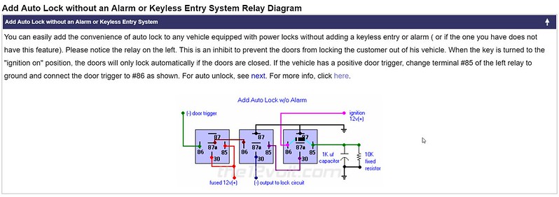
 I understand the diagram, EXCEPT for the capacitor and resistor hookup. Below is a crude representation of how I interpret it:
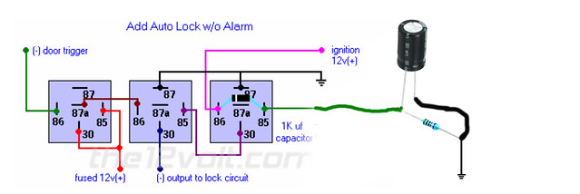 Is the above diagram correct?
Next, my presumption is that it would output a constant negative when the door is closed and the ign is on. I need a momentary negative. So I found this:
Is the above diagram correct?
Next, my presumption is that it would output a constant negative when the door is closed and the ign is on. I need a momentary negative. So I found this:
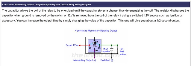 I am assuming that the switched negative from above would feed to the negative output to lock circuit on the previous diagram. Correct?
I presume that if my first interpretation of how the resistor and capacitor wire up it would be the same for the above diagram. I also presume that I would need to capacitor and resistor for BOTH relays. Would that be correct?
And finally, I would like to verify that
I am assuming that the switched negative from above would feed to the negative output to lock circuit on the previous diagram. Correct?
I presume that if my first interpretation of how the resistor and capacitor wire up it would be the same for the above diagram. I also presume that I would need to capacitor and resistor for BOTH relays. Would that be correct?
And finally, I would like to verify that 


If you wish to post a reply to this topic, you must first login.
If you are not already registered, you must first register.
 Printable version


| You cannot post new topics in this forum You cannot reply to topics in this forum You cannot delete your posts in this forum You cannot edit your posts in this forum You cannot create polls in this forum You cannot vote in polls in this forum |

| Search the12volt.com |
Follow the12volt.com 
Friday, April 19, 2024 • Copyright © 1999-2024 the12volt.com, All Rights Reserved • Privacy Policy & Use of Cookies

Friday, April 19, 2024 • Copyright © 1999-2024 the12volt.com, All Rights Reserved • Privacy Policy & Use of Cookies
Disclaimer:
*All information on this site ( the12volt.com ) is provided "as is" without any warranty of any kind, either expressed or implied, including but not limited to fitness for a particular use. Any user assumes the entire risk as to the accuracy and use of this information. Please
verify all wire colors and diagrams before applying any information.
