the12volt.com spacer
icon

Viper 5305V Trunk Release Negative Output Problem, 1990 Ford Mustang


Post ReplyPost New Topic
< Prev Topic Next Topic >
redfox90 
Member - Posts: 16
Member spacespace
Joined: May 21, 2019
Location: Florida, United States
Posted: May 31, 2019 at 6:11 PM / IP Logged Link to Post Post Reply Quote redfox90
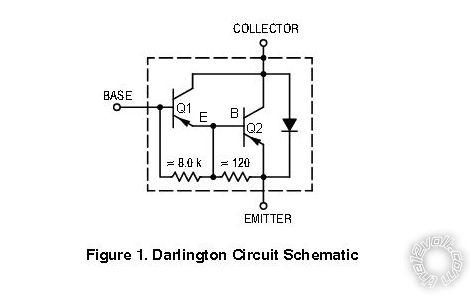
If I did wire up 2 of the transistors I have just to see if it works temporarily which transistor should I hook up the wires to? The first or the second? I understand that the first one sends the power into the second one and it basically gets amplified/increased when it comes out of the second. Would both transistors get grounded or no?
I was able to find the Tip125 Pnp transistor and I’m gonna order it if I can’t get my current ones to work.
geepherder 
Platinum - Posts: 3,668
Platinum spaceThis member consistently provides reliable informationspace
Joined: October 27, 2003
Posted: May 31, 2019 at 6:31 PM / IP Logged Link to Post Post Reply Quote geepherder
You can try, but I don't think it will work properly without the right resistors. I've modified the picture so it's a little easier to understand. The only wire that connects to Q1 (or the first transistor) is the output from the Viper to the base. The collectors will be connected together, as you said and grounded. The emitter of Q2 (the second transistor) goes to the relay coil, the other end of which goes to positive 12 volts.
Viper 5305V Trunk Release Negative Output Problem, 1990 Ford Mustang - Page 4 - Last Post -- posted image.
My ex once told me I have a perfect face for radio.
redfox90 
Member - Posts: 16
Member spacespace
Joined: May 21, 2019
Location: Florida, United States
Posted: May 31, 2019 at 6:36 PM / IP Logged Link to Post Post Reply Quote redfox90
Ok thanks, that’s way easier to understand now. I’m gonna try to do that this weekend and post an update. Either case I’m gonna just order the other transistor as well, as a backup
catback 
Silver - Posts: 703
Silver spacespace
Joined: August 13, 2002
Location: Canada
Posted: June 01, 2019 at 1:15 PM / IP Logged Link to Post Post Reply Quote catback
Sounds like you have a bad ground or a bad module. All the aux outputs are capable of triggering any general automotive electrical relay. Make sure you have a solid ground that can carry current. If you have a good solid ground and good power and the problem persists, get the viper replaced if possible because it's defective.
redfox90 
Member - Posts: 16
Member spacespace
Joined: May 21, 2019
Location: Florida, United States
Posted: June 07, 2019 at 11:48 AM / IP Logged Link to Post Post Reply Quote redfox90
Well update, after receiving the darlington pnp transistor and having no luck I began testing aux output wires and to my surprise I was able to locate an aqua blue/black wire that was able to trigger the trunk with the help of the relay, pnp transitor and a 1k resister. After securing everything my trunk pop now works. I want to thank everyone that helped me to figure this issue out.
jim2467 
Member - Posts: 2
Member spacespace
Joined: June 25, 2019
Location: North Carolina, United States
Posted: June 26, 2019 at 6:21 AM / IP Logged Link to Post Post Reply Quote jim2467
Redfox90,
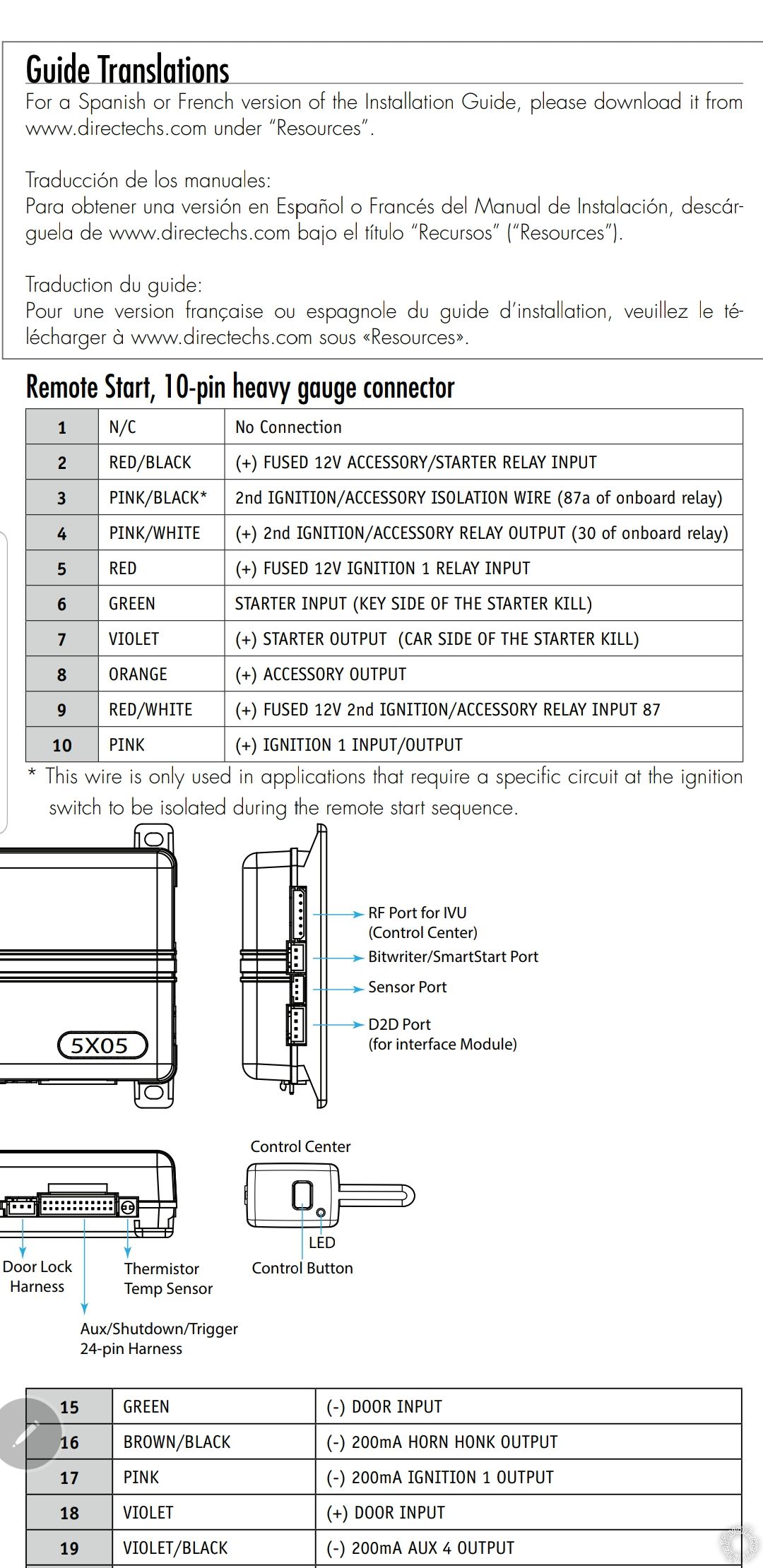
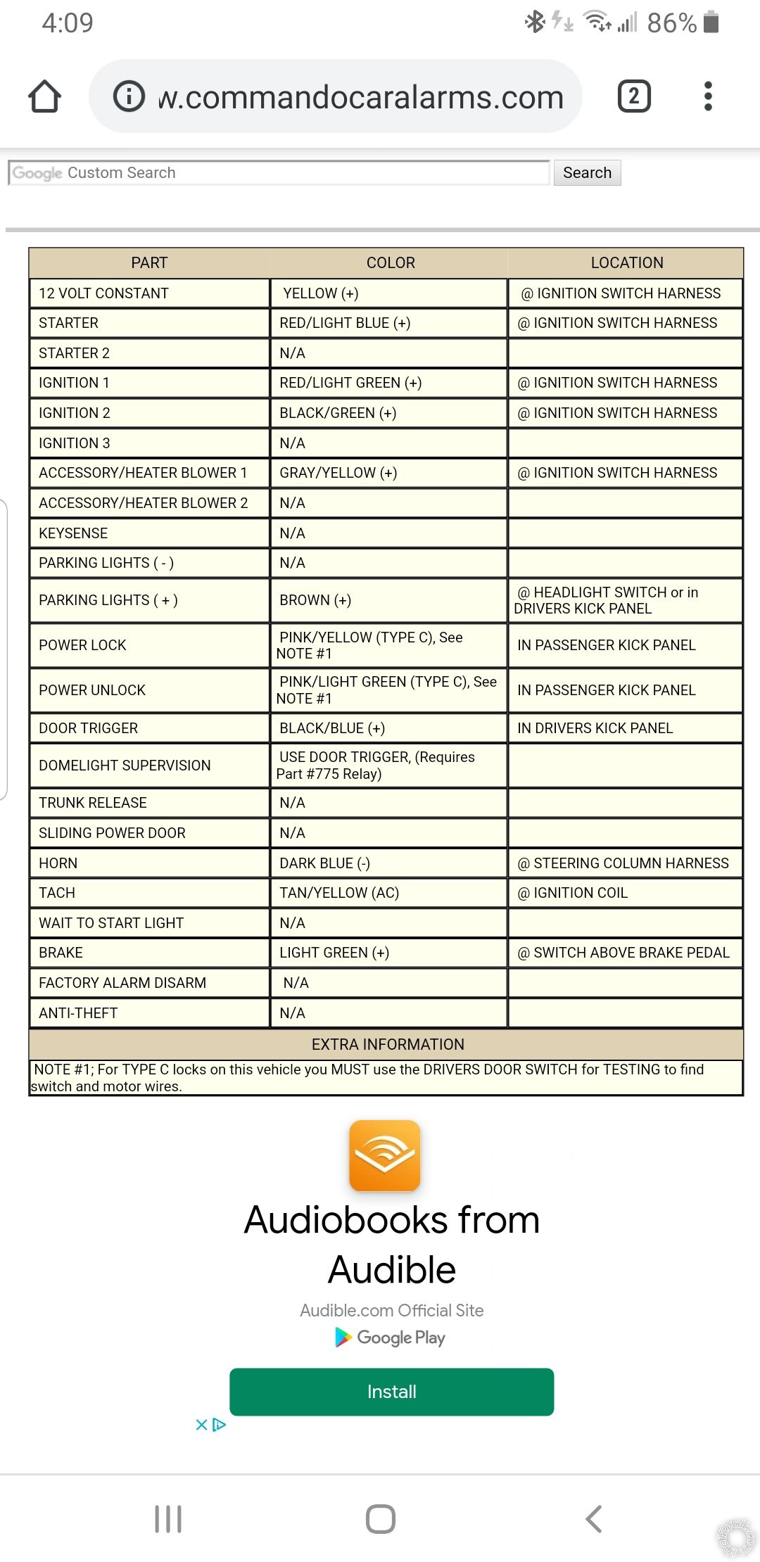
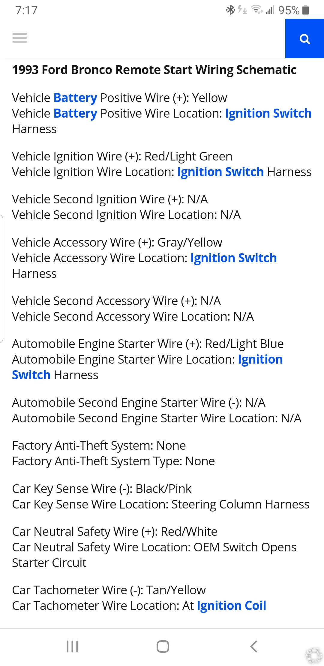
I was just reading some of your posts. May I ask how you wired your remote start? The Remote Start, 10-pin heavy gauge connector? I purchased the Python 5305P which is made by DEI, which makes Viper also. The wiring is pretty much identical. I think that the Red/Black, Red, Red/White wires go to a 12v (+) constant. And I think a 12v (+) constant with a 20 amp fuse should go to pin 87 on a relay. And the #21 pin in the 24 pin harness which is Violet/Yellow 200mA (-) starter output goes to pin 85 on a relay or a chasis ground could be used on the pin 85 or both can be used together on pin 85. And I think that the #7 pin in the 10 pin harness which is the Violet (+) starter output (car side of the starter kill) wire goes to pin 86 on the relay. I think that the #4 pin on the 10 pin harness the Pink/White 2nd ignition/accessory relay output wire goes to pin 30 on a relay. I am just not sure about the pin 6 green starter input (key side of the starter kill wire) in the 10 pin harness and where to connect it and the #8 pin orange (+) accessory output wire in the 10 pin harness and the #10 pin Pink ignition 1 input/output wire in the 10 pin harness. I have the remote keyless entry and the alarm working perfectly and flawlessly. I just cant get the remote start to work. I have a 1993 Ford Bronco 5.8 liter 4x4 Eddie Bauer's Edition. I have the wiring diagram for my Bronco and wire color codes and the Python 5305P install wiring diagram. Any help would be greatly appreciated. Viper 5305V Trunk Release Negative Output Problem, 1990 Ford Mustang - Page 4 - Last Post -- posted image.Viper 5305V Trunk Release Negative Output Problem, 1990 Ford Mustang - Page 4 - Last Post -- posted image.Viper 5305V Trunk Release Negative Output Problem, 1990 Ford Mustang - Page 4 - Last Post -- posted image.Viper 5305V Trunk Release Negative Output Problem, 1990 Ford Mustang - Page 4 - Last Post -- posted image.
Signature preview
catback 
Silver - Posts: 703
Silver spacespace
Joined: August 13, 2002
Location: Canada
Posted: June 26, 2019 at 11:06 AM / IP Logged Link to Post Post Reply Quote catback
jim2467 wrote:
Redfox90,
And I think a 12v (+) constant with a 20 amp fuse should go to pin 87 on a relay. And the #21 pin in the 24 pin harness which is Violet/Yellow 200mA (-) starter output goes to pin 85 on a relay or a chasis ground could be used on the pin 85 or both can be used together on pin 85. And I think that the #7 pin in the 10 pin harness which is the Violet (+) starter output (car side of the starter kill) wire goes to pin 86 on the relay. I think that the #4 pin on the 10 pin harness the Pink/White 2nd ignition/accessory relay output wire goes to pin 30 on a relay.
What's with all the relays? The 10-pin remote start harness should have direct connections to the appropriate wires in the vehicle. No external/additional relays required for the remote start harness.
Page of 4

If you wish to post a reply to this topic, you must first login.
If you are not already registered, you must first register.

  Printable version Printable version Post ReplyPost New Topic
You cannot post new topics in this forum
You cannot reply to topics in this forum
You cannot delete your posts in this forum
You cannot edit your posts in this forum
You cannot create polls in this forum
You cannot vote in polls in this forum

  •  
Search the12volt.com
Follow the12volt.com Follow the12volt.com on Facebook
Friday, April 19, 2024 • Copyright © 1999-2024 the12volt.com, All Rights Reserved Privacy Policy & Use of Cookies
Disclaimer: *All information on this site ( the12volt.com ) is provided "as is" without any warranty of any kind, either expressed or implied, including but not limited to fitness for a particular use. Any user assumes the entire risk as to the accuracy and use of this information. Please verify all wire colors and diagrams before applying any information.

Secured by Sectigo
the12volt.com spacer
Support the12volt.com
Top
the12volt.com spacer