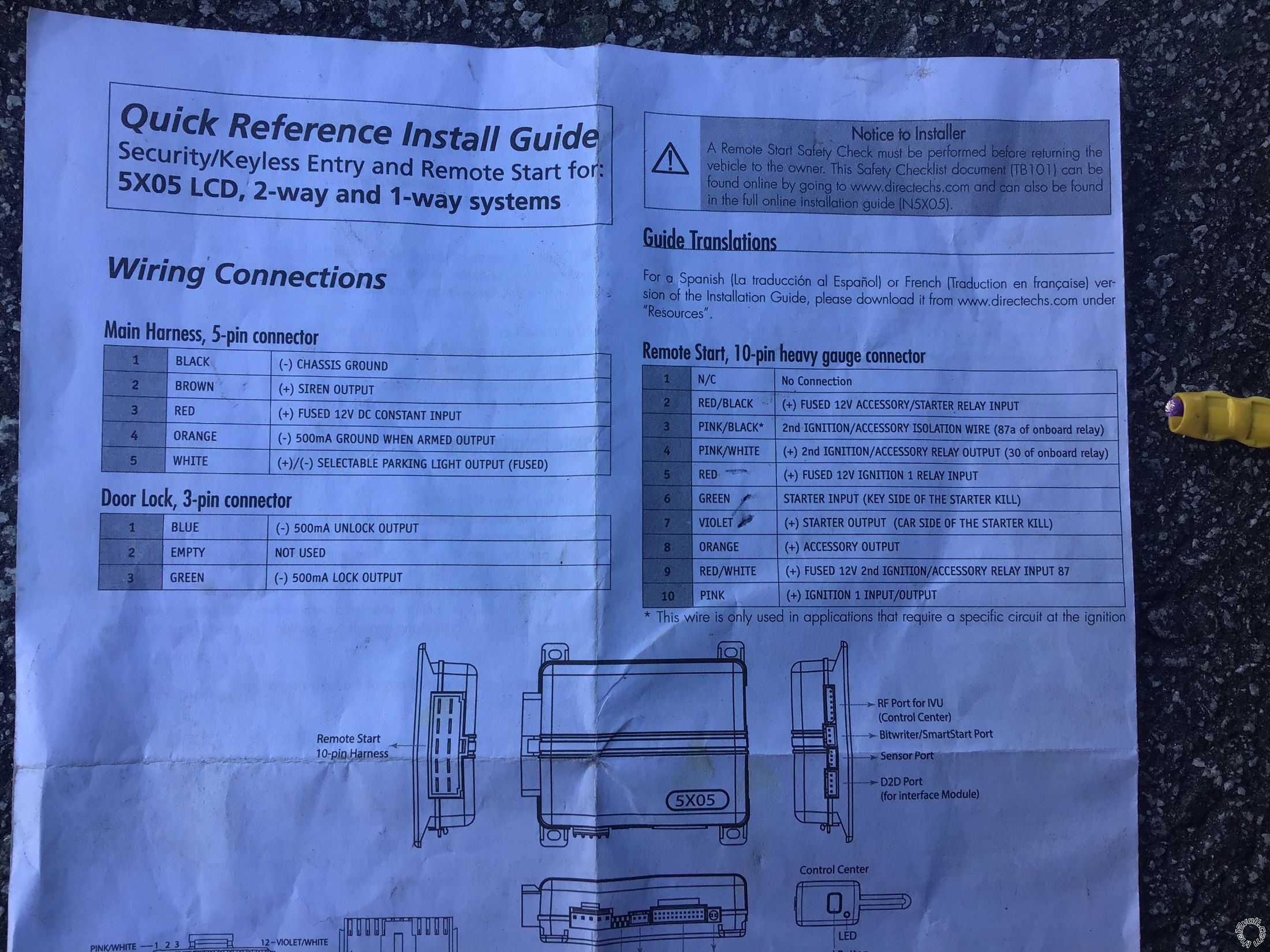
Once again, this info is only accurate if your 5103L has the same connectors and pin/wire connections as shown in the 5X05 Install Guide.
Main Harness, White 5-pin connector
1 BLACK (-) CHASSIS GROUND Chassis Ground
2 BROWN (+) SIREN OUTPUT Siren
3 RED (+) FUSED 12V DC CONSTANT INPUT +12V Constant
4 ORANGE (-) 500mA GWA Not Used
5 WHITE (+)/(-) PARKING LIGHT *Set to + Brown @ Headlight Switch
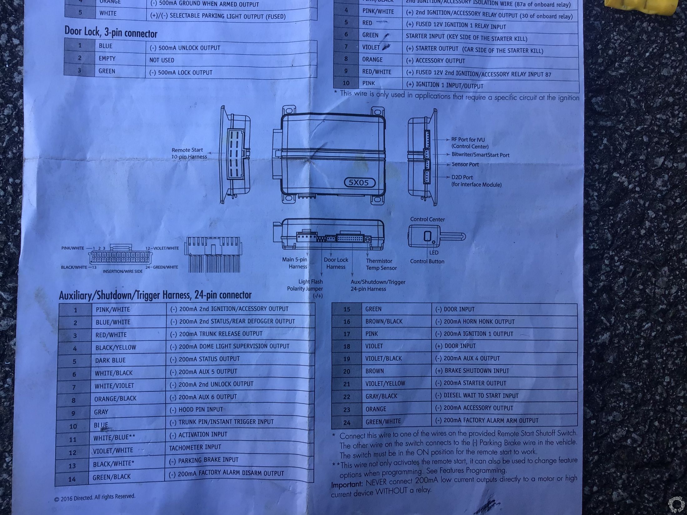
Auxiliary/Shutdown/Trigger Harness, White 24-pin connector
1 PNK/WHITE (-) 200mA IGNITION 2/ACC Not Used
2 BLUE/WHITE (-) 200mA 2ND STATUS /REAR DEFOG Not Used
3 RED/WHITE (-) 200mA TRUNK RELEASE OUTPUT Black(+) @ Trunk Switch Must use relay to convert (-) to (+)
https://www.wiresheet.com/v3/diagrams200/231%20-%20Positive%20Pulse%20Trunk%20Release%20Circuit.pdf
4 BLACK/YELLOW (-) 200mA DOME LIGHT OUTPUT Not Used
5 DARK BLUE (-) 200mA STATUS OUTPUTNot Used
6 WHITE/BLACK (-) 200mA AUX 5 OUTPUT Not Used
7 WHITE/VIOLET (-) 200mA 2nd UNLOCK OUTPUT Not Used
8 ORANGE/BLACK (-) 200mA AUX 6 OUTPUT Not Used
9 GRAY (-) HOOD PIN INPUT Kit supplied Hood Pin
10 BLUE (-) TRUNK PIN/INSTANT TRIGGER INPUT No info found. Use the Trunk Light, might need a relay
11 WHITE/BLUE (-) REMOTE START ACTIVATION INPUT Not Used
12 VIOLET/WHITE TACHOMETER INPUT White @ Coil
13 BLACK/WHITE* (-) PARKING BRAKE Chassis Ground if Auto Trans
14 GREEN/BLACK (-) 200mA FACTORY ALARM DISARM Not Used
15 GREEN (-) DOOR INPUT White = Drivers Door Pin *
16 BROWN/BLACK (-) 200mA HORN HONK OUTPUT Black at Steering Column
17 PINK (-) 200mA IGNITION 1 OUTPUT Not Used
18 VIOLET (+) DOOR INPUT Not Used
19 VIOLET/BLACK (-) 200mA AUX 4 OUTPUT Not Used
20 BROWN (+) BRAKE SHUTDOWN INPUT White @ Brake Pedal Switch
21 VIOLET/YELLOW (-) 200mA STARTER OUTPUT Not Used
22 GRAY/BLACK (-) DIESEL WTS (WAIT-TO-START) INPUT Not Used
23 ORANGE (-) 200mA ACCESSORY OUTPUT Not Used
24 GREEN/WHITE (-) 200mA FACTORY ALARM ARM OUTPUT Not Used
* This is only the Drivers Door Pin. I have no info on the Passengers Door Pin wire. For proper alarm coverage you should use both door pin wires and diode isolate them.
Remote Start, White 10-pin heavy gauge connector
1 No Connection
2 RED/BLACK (+) FUSED 12V ACCESSORY/STARTER INPUT +12V Constant
3 PINK/BLACK* (+) IGNITION 2 pin 87aNot Used
4 PINK/WHITE (+) IGNITION 2 / ACCESSORY2 Brown Program to ACC2
5 RED (+) FUSED 12V IGNITION 1 INPUT +12V Constant
6 GREEN (+) STARTER INPUT (KEY SIDE) Purple **
7 VIOLET (+) STARTER OUTPUT (CAR SIDE) Purple ***
8 ORANGE (+) ACCESSORY OUTPUT Orange
9 RED/WHITE (+) FUSED 12V IGNITION 2 +12V Constant
10 PINK (+) IGNITION 1 INPUT/OUTPUT Pink
** If you want Starter Kill and Anti-Grind, cut the Monte's Purple wire and make the connections shown using both Green and Violet wires.
*** If you don't want Starter Kill and Anti-Grind, don't cut the Mointe's Purple Starter wire, don't use the 5103's Green wire and connect only the 5103's Violet wire to the uncut Purple wire.
Door Lock, White 3-pin connector
1 BLUE (-) 500mA UNLOCK OUTPUT To 451M module
2 EMPTY NOT USED
3 GREEN (-) 500mA LOCK OUTPUT To 451M module
If I remember correctly, the SS version had a LG4 305 CI engine with a Rochester carburetor with around 180 HP. The big question is if the gas pedal needs to be depressed and released to set the choke prior to starting the engine.
Soldering is fun!


 Second part of it is ..
 Everything should be wired the same as what you told me right? Not trying to pop fuses and let the mask. Smoke out .. ohh ant the door lock relay is a 451m model sorry about that
 Printable version


