the12volt.com spacer
icon

1993 Ford Mustang, Keyless Entry


Post ReplyPost New Topic
< Prev Topic Next Topic >
getbigmatt 
Member - Posts: 5
Member spacespace
Joined: November 08, 2020
Location: Texas, United States
Posted: November 08, 2020 at 7:04 PM / IP Logged Link to Post Post Reply Quote getbigmatt
Hello all, I've been following this thread closely as I'm attempting to install the exact same keyless entry product as the original poster into my 1993 Mustang. I would like to do the install without the additional relays as previously mentioned it appears this unit has relays built into the brain.
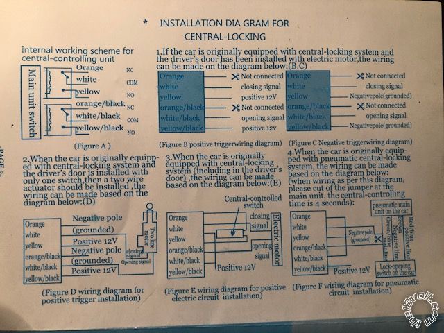
I have located the pink/yellow and pink/green wires that I need to cut; however I'm lost as to which wires I need to connect where on the keyless entry harness. Can someone please explain which wires go where without using additional relays? Here are the diagram options/instructions that came with the unit. I believe I should be following figure E? The car does have original equipment power locks.
1993 Ford Mustang, Keyless Entry - Last Post -- posted image.
kreg357 
Platinum - Posts: 7,783
Platinum spaceThis member has made a donation to the12volt.com. Click here for more info.spaceThis member has been recognized as an authority in Electrical Theory. Click here for more info.spaceThis member has been recognized as an authority in Mobile Security and Convenience. Click here for more info.spacespace
Joined: January 30, 2009
Location: Pennsylvania, United States
Posted: November 09, 2020 at 7:10 AM / IP Logged Link to Post Post Reply Quote kreg357
I'm thinking you can do it with just the aftermarket RKE unit alone. It appears to have internal relays. The upper set of wires ( Orange, Whire, Yellow ) is for Lock and the lower set ius you unlock.
The car has a positive 5 wire reverse system.
First you must local, cut and test the cars lock wires. You must determine which side of the cut wire is the motor side. Use the test shown in the post you linked. The wiring will be like this :
Combine the Yellow and Yellow/Black and connect them to +12V constant through a 15 amp fuse.
White wire to motor side of cut Lock wire.
Orange wire to switch side of cut Lock wire
White/Black wire to motor side of cut Unlock wire.
Orange/Black wire to switch side of cut Unlock wire.
That should do it.
Soldering is fun!
getbigmatt 
Member - Posts: 5
Member spacespace
Joined: November 08, 2020
Location: Texas, United States
Posted: November 09, 2020 at 8:13 AM / IP Logged Link to Post Post Reply Quote getbigmatt
@kreg357 That makes a lot of sense, thank you for the response and explanation. I'll give it a go after work and let you know if I have any issues.
getbigmatt 
Member - Posts: 5
Member spacespace
Joined: November 08, 2020
Location: Texas, United States
Posted: November 11, 2020 at 10:32 AM / IP Logged Link to Post Post Reply Quote getbigmatt
I was finally able to get the keyless entry wired up as @kreg357 explained and that part is working perfectly, THANK YOU.
I'm now having issues getting the truck release to work using a relay. I have found/tapped into the purple/yellow trunk release wire and wired my relay the below two ways without success. Can someone please tell me what I'm missing? Neither of the below wiring configurations are working for me:
86: 12v(+)
85: Trigger from RKE
30: Ground(-)
87: Lead from tapped purple/yellow trunk release wire
86: 12v(+)
85: Trigger from RKE
30: 12v(+)
87: Lead from tapped purple/yellow trunk release wire
kreg357 
Platinum - Posts: 7,783
Platinum spaceThis member has made a donation to the12volt.com. Click here for more info.spaceThis member has been recognized as an authority in Electrical Theory. Click here for more info.spaceThis member has been recognized as an authority in Mobile Security and Convenience. Click here for more info.spacespace
Joined: January 30, 2009
Location: Pennsylvania, United States
Posted: November 11, 2020 at 10:49 AM / IP Logged Link to Post Post Reply Quote kreg357
My info indicates the Trunk Release is a Purple/Yellow wire found at the trunk release switch. It needs a (+) signal. That being said, your lower listed wiring should work assuming the RKE system is outputting a (-) signal. Can you hear the relay energize? Verify the Purple/Yellow wire with a Digital Multi Meter. Make sure the +12V constant input at relay pin 30 and pin 86 have power ( they can be combined and should be fused at 15 amps ).
Soldering is fun!
getbigmatt 
Member - Posts: 5
Member spacespace
Joined: November 08, 2020
Location: Texas, United States
Posted: November 11, 2020 at 11:28 AM / IP Logged Link to Post Post Reply Quote getbigmatt
I did hear/feel the relay energize/activate when I connected the purple/yellow wire to 87 which I thought was weird, does that sounds correct too you?
I'll double check that I have the correct purple/yellow wire this evening.
kreg357 
Platinum - Posts: 7,783
Platinum spaceThis member has made a donation to the12volt.com. Click here for more info.spaceThis member has been recognized as an authority in Electrical Theory. Click here for more info.spaceThis member has been recognized as an authority in Mobile Security and Convenience. Click here for more info.spacespace
Joined: January 30, 2009
Location: Pennsylvania, United States
Posted: November 11, 2020 at 3:44 PM / IP Logged Link to Post Post Reply Quote kreg357
The relay should energize with just pins 85 and 86. Nothing needs to on any other pins to test the relay coil. Relay convention suggests that Pin 86 get the (+) signal and Pin 85 get the (-) signal like in your post. Double check the relay pins and wiring there, too. You can use the DMM Ohms setting to test the relays Pin 30 to 87 when energized and 30 to 87a contacts when not energized.
Soldering is fun!
getbigmatt 
Member - Posts: 5
Member spacespace
Joined: November 08, 2020
Location: Texas, United States
Posted: November 12, 2020 at 8:22 PM / IP Logged Link to Post Post Reply Quote getbigmatt
@Kreg357 your instructions were perfectly accurate and everything (including the trunk release) is now working as designed. Anyone else installing remote keyless entry into a Foxbody Mustang just needs to follow these directions.
THANK YOU!
jasfoxbod 
Member - Posts: 1
Member spacespace
Joined: March 08, 2021
Location: Texas, United States
Posted: March 08, 2021 at 3:16 PM / IP Logged Link to Post Post Reply Quote jasfoxbod
Thank you first of all, this made setting up my keyless entry much easier after reading so many other posts in different forums. Only question I have is related to the trunk release. So nothing needs to be connected to 87a on the relay, correct? Using this setup you confirmed for getbigmatt
86: 12v(+)
85: Trigger from RKE
30: 12v(+)
87: Lead from tapped purple/yellow trunk release wire
jas
kreg357 
Platinum - Posts: 7,783
Platinum spaceThis member has made a donation to the12volt.com. Click here for more info.spaceThis member has been recognized as an authority in Electrical Theory. Click here for more info.spaceThis member has been recognized as an authority in Mobile Security and Convenience. Click here for more info.spacespace
Joined: January 30, 2009
Location: Pennsylvania, United States
Posted: March 08, 2021 at 8:19 PM / IP Logged Link to Post Post Reply Quote kreg357
Yes, that relay wiring will work.   It converts the RKE's (-) output to a (+) signal the Mustang needs. Relay Pin 87a is not used, just insulate that wire
Soldering is fun!

If you wish to post a reply to this topic, you must first login.
If you are not already registered, you must first register.

  Printable version Printable version Post ReplyPost New Topic
You cannot post new topics in this forum
You cannot reply to topics in this forum
You cannot delete your posts in this forum
You cannot edit your posts in this forum
You cannot create polls in this forum
You cannot vote in polls in this forum

  •  
Search the12volt.com
Follow the12volt.com Follow the12volt.com on Facebook
Thursday, April 18, 2024 • Copyright © 1999-2024 the12volt.com, All Rights Reserved Privacy Policy & Use of Cookies
Disclaimer: *All information on this site ( the12volt.com ) is provided "as is" without any warranty of any kind, either expressed or implied, including but not limited to fitness for a particular use. Any user assumes the entire risk as to the accuracy and use of this information. Please verify all wire colors and diagrams before applying any information.

Secured by Sectigo
the12volt.com spacer
Support the12volt.com
Top
the12volt.com spacer