the12volt.com spacer
icon

2004 Toyota Corolla, Clutch Bypass, Viper 5806V


Post ReplyPost New Topic
< Prev Topic Next Topic >
jwestak 
Member - Posts: 1
Member spacespace
Joined: February 23, 2017
Location: Alaska, United States
Posted: August 03, 2021 at 12:35 PM / IP Logged Link to Post Post Reply Quote jwestak
Hello All,
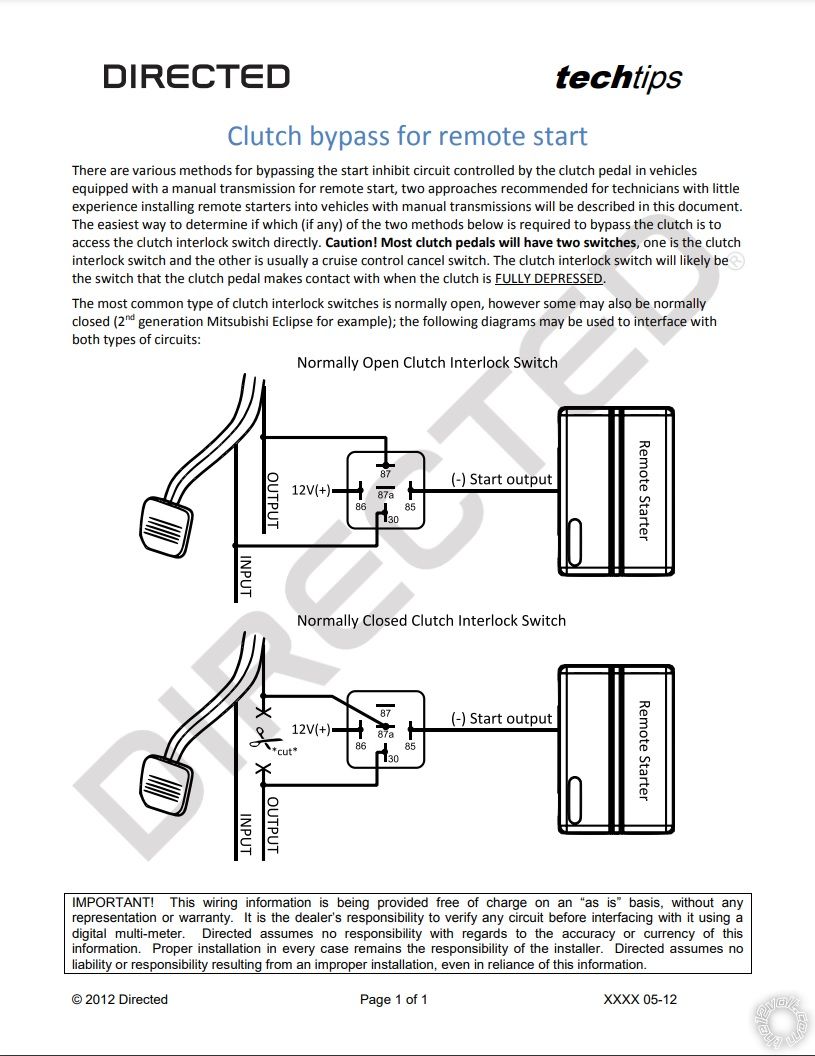
I am finishing up a Viper 5806v remote start on my 2004 Corolla and have a question about clutch bypass. The Corolla if I'm not mistaken uses a Normally Open Negative Clutch Circuit. If I am to use the Aux 200mA (-) Starter Output from my remote to trigger the clutch. Should this be done through a relay like suggested in the directed tech tip, and should I be using a diode in front of the (-) output if running a relay as shown. I want to make sure I'm not going to burn up the unit.
If anyone is wondering about the safety portion, the remote is programmed for Manual Transmission operation and I'm asking this question so I can properly bypass the clutch switch with the remote feature while retaining the normal "push clutch to key start safety".
I appreciate your help with this.
2004 Toyota Corolla, Clutch Bypass, Viper 5806V - Last Post -- posted image.
kreg357 
Platinum - Posts: 7,783
Platinum spaceThis member has made a donation to the12volt.com. Click here for more info.spaceThis member has been recognized as an authority in Electrical Theory. Click here for more info.spaceThis member has been recognized as an authority in Mobile Security and Convenience. Click here for more info.spacespace
Joined: January 30, 2009
Location: Pennsylvania, United States
Posted: August 03, 2021 at 9:37 PM / IP Logged Link to Post Post Reply Quote kreg357
You might be mistaken about the 2004 Toyota Corolla's clutch interlock. Did you test the clutch interlock switch with a DMM?
The info I have indicates that it is a N.O. (+) signal. Check the interlock switch connector. If it has two wires with one Red and one Black, verify that the Red wire has +12V* and when the clutch pedal is depressed that +12V gets passed along to the Black wire.
* test should be done with the ignition switch in the ON position
If that is your cars setup, then you can wire up your relay as shown below :
Relay Pin 85 to Viper (-) Starter Output
Relay Pins 86 and 87 to +12V through fuse
Relay Pin 30 to Black wire at clutch interlock switch
To protect the Viper's (-) Starter Output from the relays coil collapse pulse use a 1N4007 diode across the Relay pins 86 and 85 with the diodes band towards Pin 86.
Soldering is fun!

If you wish to post a reply to this topic, you must first login.
If you are not already registered, you must first register.

  Printable version Printable version Post ReplyPost New Topic
You cannot post new topics in this forum
You cannot reply to topics in this forum
You cannot delete your posts in this forum
You cannot edit your posts in this forum
You cannot create polls in this forum
You cannot vote in polls in this forum

  •  
Search the12volt.com
Follow the12volt.com Follow the12volt.com on Facebook
Thursday, April 18, 2024 • Copyright © 1999-2024 the12volt.com, All Rights Reserved Privacy Policy & Use of Cookies
Disclaimer: *All information on this site ( the12volt.com ) is provided "as is" without any warranty of any kind, either expressed or implied, including but not limited to fitness for a particular use. Any user assumes the entire risk as to the accuracy and use of this information. Please verify all wire colors and diagrams before applying any information.

Secured by Sectigo
the12volt.com spacer
Support the12volt.com
Top
the12volt.com spacer