the12volt.com spacer
icon

reverse polarity with a twist.


Post ReplyPost New Topic
< Prev Topic Next Topic >
hyperryd 
Member - Posts: 28
Member spacespace
Joined: November 12, 2006
Location: United States
Posted: March 10, 2007 at 7:00 PM / IP Logged  

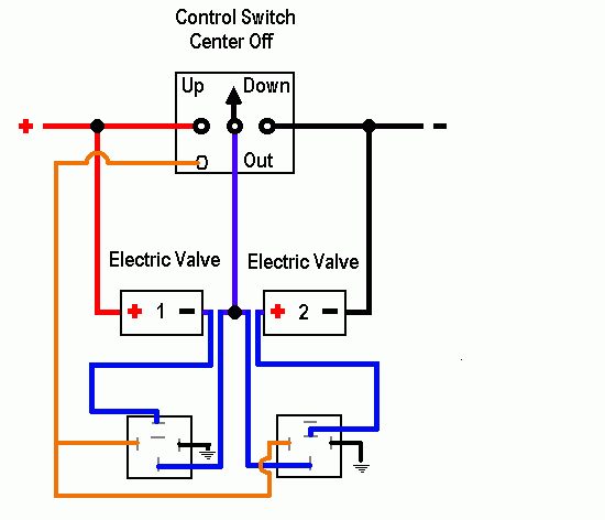
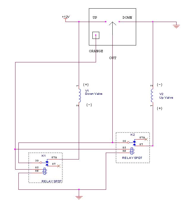
Wizard I hacked up your diagram and please realize I can't draw to save my life.  This is the configuration that ended up working out.  Valve 2 is down, valve 1 is up.  The orange wire out of the switch is hot when any of the switches are up.  When the switch is down the signal goes through the relay at rest to activate valve 2.  The relay on valve one has the signal interupted at rest so there is no feedback.  When the switch is up both valves energize from the orange wire letting the signal through to valve one and interupting valve two.  I figured it out in the shower this morning, go figure.  It works like a champ and the joystick works as well taking the whole car up or down with the joystick. 

Thanks for all of your help.  I really feel that situations like this is where a discussion board is priceless.  You can keep sounding ideas off of like minded people until someone finds the solution.

reverse polarity with a twist. - Page 5 - Last Post -- posted image.

reverse polarity with a twist. - Page 5 - Last Post -- posted image.reverse polarity with a twist. - Page 5 - Last Post -- posted image.

hyperryd 
Member - Posts: 28
Member spacespace
Joined: November 12, 2006
Location: United States
Posted: March 10, 2007 at 7:03 PM / IP Logged  
By the way the diagram is for one of the rocker switches to control one end of the car.  I did exactly the same thing for the other switch to control the other set of valves.  There were four valves in all, controlled by two rocker switches that basically make the car go up or down like a power window switch.
hotwaterwizard 
Silver - Posts: 1,350
Silver spacespace
Joined: December 11, 2003
Location: California, United States
Posted: March 10, 2007 at 7:07 PM / IP Logged  

Great.

Where did this orange wire come from.

It would have been nice to have known about that before aswell as the application.

Any time you need me just Email me hotwaterwizard@aol.com

You can instant message me on AOL or AIM at my nickname hotwaterwizard

John DeRosa (Hotwaterwizard)
Stockton California
When in doubt, try it out !
hyperryd 
Member - Posts: 28
Member spacespace
Joined: November 12, 2006
Location: United States
Posted: March 10, 2007 at 7:47 PM / IP Logged  

John, I think all of us were tired and skipping posts and posting at the same time last night.  If you look back at the end of page 2, I described the switch set up and application and on the page 3 right before your diagram I described the extra two wires. 

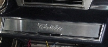
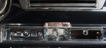
Again I appreciate all of your help working through this.  It works great and looks like it came from the factory in 1965.

hotwaterwizard 
Silver - Posts: 1,350
Silver spacespace
Joined: December 11, 2003
Location: California, United States
Posted: March 10, 2007 at 10:00 PM / IP Logged  

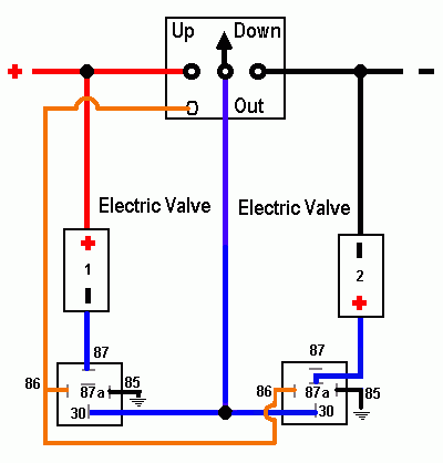
I fixed up the Drawing of your final design for you. Nice job.

reverse polarity with a twist. - Page 5 - Last Post -- posted image.

John DeRosa (Hotwaterwizard)
Stockton California
When in doubt, try it out !
dualsport 
Silver - Posts: 983
Silver spacespace
Joined: September 27, 2005
Location: United States
Posted: March 11, 2007 at 12:29 AM / IP Logged  
I glossed over the orange wire too, but it doesn't matter, since you could have done the same thing with the use of the signal output to control the two relays- nice and simple, good going!
hotwaterwizard wrote:

I fixed up the Drawing of your final design for you. Nice job.

reverse polarity with a twist. - Page 5 - Last Post -- posted image.

At first I thought the terminology of switch being 'up' meant off, or in the standby condition, but then realized up meant the pushing of the switch to command the suspension to go up.
If I have it straight, I think the connections for 87 and 87A connections should be reversed in the diagram- valve 1 (-) should go to 87A rather than 87, and valve 2 (+) should go to 87 rather than 87A.
And valve 2 should then be Up, valve 1 is Down.
hyperryd 
Member - Posts: 28
Member spacespace
Joined: November 12, 2006
Location: United States
Posted: March 11, 2007 at 10:17 AM / IP Logged  

The problem with using the signal wire to activate the valves it I still ended up with that feedback across the coil of the relays as well.  As soon as you activated one relay the other one would energize at the same time.  Using the orange wire eliminated that.  I still don't understand why there was enough reverse polarity energy feeding back to activate the oposite coil so much, but sometimes you just have to work around a problem. 

As for the diagram, I don't deal with diagrams much, but I think it is right.  When the switch is down the signal flows throught the 87a to the down valve.  When any switch is up the orange wire is hot, which energizes both relays that disconnects valve 2 and lets the signal to open valve 1 through.

It's amazing how when describing a problem to other people, when they can't see the situation, how hard it is to make sure that everybody understands the whole picture.  Because I am looking at it,  I take for granted that the other person knows what I am doing, and where I want it to go.  There are times that I think I have given enough of a description, to solve the problem, but without being right there it is tough to grasp the little things that the person who is present sees.  I do appreciate everybody's help though, it really helps get the mind going outside the box of the problem that you are staring blindly at when you have other educated opinions.  I knew this could be done, but it was kicking my a**.

dualsport 
Silver - Posts: 983
Silver spacespace
Joined: September 27, 2005
Location: United States
Posted: March 11, 2007 at 2:58 PM / IP Logged  
Yeah, the separate orange wire is needed since the valve 1 would otherwise feed 12V to the relay coil K1 in the standby state.
This is what I figured you had worked out, with the NC and NO connections flipped.
reverse polarity with a twist. - Page 5 - Last Post -- posted image.
overworked2 
Copper - Posts: 132
Copper spacespace
Joined: March 10, 2005
Location: United States
Posted: March 27, 2007 at 2:58 PM / IP Logged  
phew....I'm glad thats over!
Check all advice given with a meter
Page of 5

Sorry, you can NOT post a reply.
This topic is closed.

  Printable version Printable version Post ReplyPost New Topic
You cannot post new topics in this forum
You cannot reply to topics in this forum
You cannot delete your posts in this forum
You cannot edit your posts in this forum
You cannot create polls in this forum
You cannot vote in polls in this forum

  •  
Search the12volt.com
Follow the12volt.com Follow the12volt.com on Facebook
Thursday, April 25, 2024 • Copyright © 1999-2024 the12volt.com, All Rights Reserved Privacy Policy & Use of Cookies
Disclaimer: *All information on this site ( the12volt.com ) is provided "as is" without any warranty of any kind, either expressed or implied, including but not limited to fitness for a particular use. Any user assumes the entire risk as to the accuracy and use of this information. Please verify all wire colors and diagrams before applying any information.

Secured by Sectigo
the12volt.com spacer
Support the12volt.com
Top
the12volt.com spacer