the12volt.com spacer
icon

multiple relays share same common output


Post ReplyPost New Topic
< Prev Topic Next Topic >
frans-c 
Copper - Posts: 77
Copper spacespace
Joined: February 14, 2006
Location: South Africa
Posted: July 31, 2007 at 1:41 PM / IP Logged  
phonymike, thanks a lot! I actually thought of using a setup similar to the one you drew there, but like you said, I thought it would be a waste of the on-board relays.
And yes, I also realised that the diodes would nullify the grounding capabilities of the other relays.
All that's left to do know is to execute the master plan... multiple relays share same common output - Page 2 - Last Post -- posted image.
F R A N S
1985 Mercedes-Benz 230E
320 000 km / 199 000 miles
Full MB Service History
frans-c 
Copper - Posts: 77
Copper spacespace
Joined: February 14, 2006
Location: South Africa
Posted: August 01, 2007 at 6:54 AM / IP Logged  
I took another look at my diagram, as well as the one of phonymike's and came to the conclusion that neither my original diagram, nor the one that he proposes, is going to work.
The reason is that the switch supplies a negative trigger, whereas the 712T's on-board relays supply a positive 12V. I'm not too familiar yet with relays, but I'm almost certain a relay can't be triggered by a positive and negative trigger at the same time, can it?
I concluded that the positive 12V of the 712T's output first has to be converted to a negative trigger. Only then will I be able to use both the switch and relay's output to trigger the relays.
This is the diagram that I came up with:
multiple relays share same common output - Page 2 - Last Post -- posted image.
F R A N S
1985 Mercedes-Benz 230E
320 000 km / 199 000 miles
Full MB Service History
phonymike 
Member - Posts: 29
Member spacespace
Joined: June 20, 2007
Location: United States
Posted: August 01, 2007 at 8:29 AM / IP Logged  
again this is an assumption since you cannot provide me with more information on the module, but I assume the 'driver's unlock' is actually +unlock, -lock, while the 'all doors lock' is actually -unlock, +lock. what you should do is hook the module up. then read the two outputs with a multi meter. they should both show ground. then trigger it to unlock, one of them should show 12+. then trigger it to lock, the other should show 12+. if this is the case then my diagram will work.
frans-c 
Copper - Posts: 77
Copper spacespace
Joined: February 14, 2006
Location: South Africa
Posted: August 01, 2007 at 9:46 AM / IP Logged  
phonymike, here's the wiring harness from the 712T installation manual:
multiple relays share same common output - Page 2 - Last Post -- posted image.
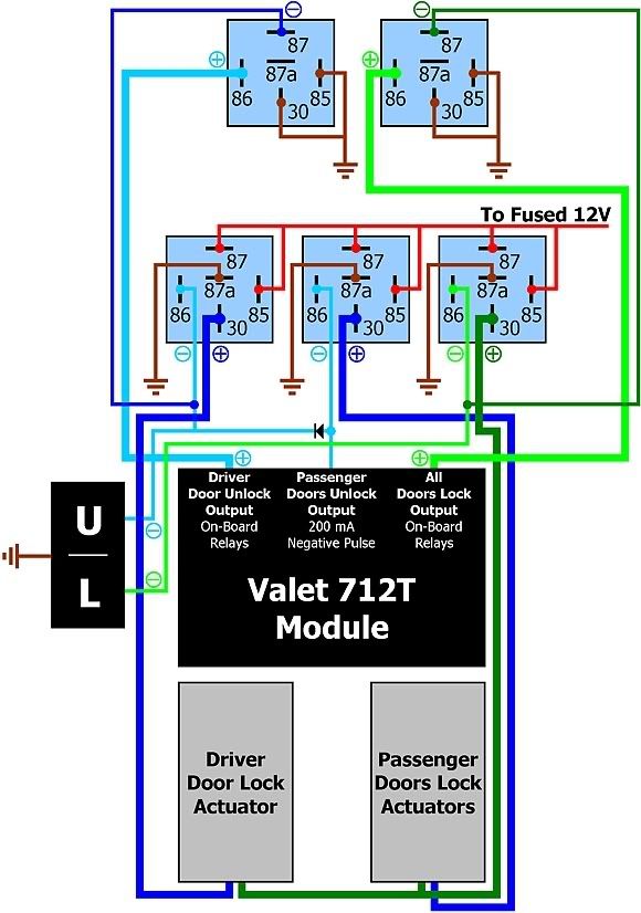
I'm almost certain that the common output terminals deliver positive 12V voltage.
F R A N S
1985 Mercedes-Benz 230E
320 000 km / 199 000 miles
Full MB Service History
phonymike 
Member - Posts: 29
Member spacespace
Joined: June 20, 2007
Location: United States
Posted: August 01, 2007 at 11:14 AM / IP Logged  
boom that's what I'm talkin bout! now all you need is one relay for the second unlock and you're done, you just treat internal relays like you would normal ones.
frans-c 
Copper - Posts: 77
Copper spacespace
Joined: February 14, 2006
Location: South Africa
Posted: August 01, 2007 at 1:37 PM / IP Logged  
phonymike, what about my door lock switch then? Surely I'll have to incorporate at least three additional relays, considering that I'd like priority door unlocking.
That last post of yours was a bit vague...what did you mean by it exactly?
F R A N S
1985 Mercedes-Benz 230E
320 000 km / 199 000 miles
Full MB Service History
phonymike 
Member - Posts: 29
Member spacespace
Joined: June 20, 2007
Location: United States
Posted: August 02, 2007 at 3:32 AM / IP Logged  

yeah you're right, you still need 3 relays, and we'll just use the module to supply a ground output from the keyless, and tie it into your switch.

  • blue/black -> first relay 86 + switch (driver unlock)
  • violet -> ground (source for unlock, throws a ground like your switch)
  • blue -> second relay 86 + diode to driver's unlock wire/switch (pass unlock)
  • GREEN/ black -> third relay 86 + switch (locks doors)
  • violet/black -> ground (provides a ground to lock the doors)

use that and my diagram and you'll be set!

frans-c 
Copper - Posts: 77
Copper spacespace
Joined: February 14, 2006
Location: South Africa
Posted: August 02, 2007 at 5:34 AM / IP Logged  
That makes sense, yes!
Am I correct when I say that in the normally closed state, the modules on-board door lock relays should then rest at open, i.e. both terminals #87a (H1/6 and H1/17) will then not be used at all? (I only see know that Directed made a printing error with the description of wire H1/6 multiple relays share same common output - Page 2 - Last Post -- posted image. .)
When the coils of the on-board relays are energised, it will switch to normally open, thereby supplying the ground pulse to the other relays, right?
F R A N S
1985 Mercedes-Benz 230E
320 000 km / 199 000 miles
Full MB Service History
Page of 2

Sorry, you can NOT post a reply.
This topic is closed.

  Printable version Printable version Post ReplyPost New Topic
You cannot post new topics in this forum
You cannot reply to topics in this forum
You cannot delete your posts in this forum
You cannot edit your posts in this forum
You cannot create polls in this forum
You cannot vote in polls in this forum

  •  
Search the12volt.com
Follow the12volt.com Follow the12volt.com on Facebook
Thursday, April 18, 2024 • Copyright © 1999-2024 the12volt.com, All Rights Reserved Privacy Policy & Use of Cookies
Disclaimer: *All information on this site ( the12volt.com ) is provided "as is" without any warranty of any kind, either expressed or implied, including but not limited to fitness for a particular use. Any user assumes the entire risk as to the accuracy and use of this information. Please verify all wire colors and diagrams before applying any information.

Secured by Sectigo
the12volt.com spacer
Support the12volt.com
Top
the12volt.com spacer