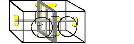
From your description and OD dimensions shown in the pics, it appears that you aren't figuring in the displacement of bracing. You will need some serious braces in a box that large made with 3/4" MDF. At least one at center going front to back, and one going side to side. Here is example of the concept, where the yellow areas show the weakest flex points, but you should modify it to suit the build. Solid-piece constructed baffles in both directions and centered, very large cutouts in each, would be good bracing.
I've also seen some nice bracing made where the side to side brace is designed to provide support for the heavy back ends of the woofers. That concept takes a great deal of strain off the front baffle. I would probably use one of those along with a large cutout front to back center brace. Ideal is to have bracing attached to the centers of every large expanse.
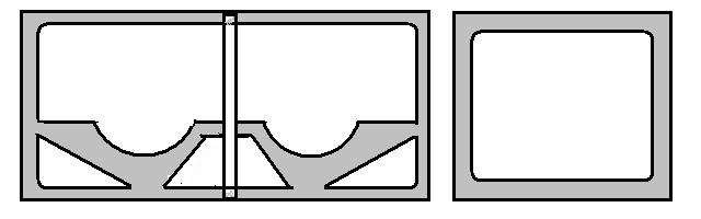
Kind of like these. Simplest thing to do, though, is just use the large cutout braces. Solid piece of 3/4" MDF or plywood with center cut out. Glue one brace to fit front to back of box and centered between the front baffle cutouts (it will also fit firmly against top and bottom). Then fit one from center brace to port wall (if port wall length reaches the halfway point of the box). Then the third brace from center to the other outside wall. You just have to do the best you can in figuring cubic inches of brace material. I usually can find it easier to measure the cubic inches of the pieces that are cut out of the brace and deduct the sum from the total cu inches of the original piece of MDF that was cut to fit.
You also have to deduct the proper displacement for the drivers. Those should be slightly more than .1 cu ft each. And, displacement for port and additional port structure wall have to be deducted. If, and it looks to be likely, your 6.6 cu ft box goes down to 5.5 cu ft when all displacements are taken out (including what I'm going to say in the next paragraph), you will be figuring port size for that amount of net airspace to get the 35 Hz.
Now, about port size. The opening area in your pic is possibly too small for those subs, at 29 sq in. (14.5 X 2 ). I would move the opening width to 3.5", and so make the opening about 50 sq inches, or about the same as an 8" diameter round port. This will increase the port length (to about 14.25") which I like to be longer than 4" anyway. With longer length there is less concern for getting the length to the exact millimeter...more room for error. This greater port volume, assuming a .75" separating wall, amounts to about .45 cu ft which I allowed in what I said above about getting a final net airspace of 5.5 cu ft.
You will note that the smaller the net air volume of the box becomes, the longer the port becomes to achieve desired Fb. Change box airspace from 6.5 to 5.5 in the calculators for a quick look at that. You might even want to eventually drop the port width down to about 3" so that the port displacement gets smaller and the box airspace gets bigger. There's a lot of back and forth in getting to the final design of a vented box.
With that, you should see if the response you get with 5.5 cu ft tuned at 35 Hz is suitable for what you're looking for. I'm not up to working this all out in WinISD, but if you actually need to have over 6 cu ft of airspace for those two subs you should start out with larger dimensions so you can incorporate the bracing and longer port structure that I emphasized.
Don't miss reading the sticky subject What is a proper sub box?
Build the box so that it performs well in the worst case scenario and, in return, it will reward you at all times.


 Printable version


