the12volt.com spacer
icon

Grounding confusion


Post ReplyPost New Topic
< Prev Topic Next Topic >
12vdeej 
Member - Posts: 26
Member spacespace
Joined: July 04, 2006
Location: United Kingdom
Posted: July 22, 2006 at 2:12 PM / IP Logged  
according to the 'What is a proper ground?' sticky, a decent ground should have a resistance of 1/2 an ohm or less. What confuses me is how even a fairly low power amp can run with a ground resistance of 1/2 an ohm. Using ohms law the maximum current draw would be: 14.4 volts/0.5 ohms = 28.8 amps. Only low power amps will draw this little current ( in the region of 200W rms output). How can larger amps function with a ground resistance of 1/2 an ohm? Before i fixed the problem, the ground resistance to my qtx 200 was a large 3.2 ohms which should allow a maximum current draw of 14.4 volts/ 3.2 ohms = 4.5 amps, yet it appeared to function fully and now that i have fixed the high resistance ground problem it doesnt appear to work any better. can anyone explain this? thanks
stevdart 
Platinum - Posts: 5,816
Platinum spaceThis member has made a donation to the12volt.com. Click here for more info.spaceThis member has been recognized as an authority in Mobile Audio and Video. Click here for more info.spaceThis member consistently provides reliable informationspace
Joined: January 24, 2004
Location: Pennsylvania, United States
Posted: July 22, 2006 at 4:22 PM / IP Logged  
You're mixing the wrong variables in an Ohm's Law formula.  To find amperage draw of your amplifier, first set the gains correctly and then measure voltage output of the amplifier into the load using a pure sine wave and with the load disconnected.  Once you know the voltage output, use Ohm's Law I = E/R to find the current draw.  R is the impedance of the load.
Build the box so that it performs well in the worst case scenario and, in return, it will reward you at all times.
12vdeej 
Member - Posts: 26
Member spacespace
Joined: July 04, 2006
Location: United Kingdom
Posted: July 23, 2006 at 6:00 AM / IP Logged  

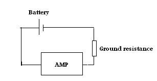
The explaination you gave would surely be for the output current, seeing as you are using the output votlage and the load resistance to calculate the current? I am talking about the input current draw. The diagram below shows the grounding resistance modelled as a resistor. Seeing as the amp is in series with the 'grounding resistor', the maximum current the amp can draw is determined by the sum of the resistance of the ground and and the amp's own impedance. Hopefully this helps to explain the problem more clearly.

       Grounding confusion -- posted image.

stevdart 
Platinum - Posts: 5,816
Platinum spaceThis member has made a donation to the12volt.com. Click here for more info.spaceThis member has been recognized as an authority in Mobile Audio and Video. Click here for more info.spaceThis member consistently provides reliable informationspace
Joined: January 24, 2004
Location: Pennsylvania, United States
Posted: July 23, 2006 at 9:39 AM / IP Logged  

Yeah, that's why I try to tackle these kinds of problems.  It confuses me, so I have to sort it all out every time.  Some day maybe it will come quick and easy. 

I think I would have had to first determine power output of the amplifier, then use the voltage at the battery as E to find current draw.  The efficiency of the amplifier would have had to be calculated, as well.  And it seems reasonable, in a sense, to add the resistance of the ground circuit to the resistance of the device (as you displayed above) to find an answer, but that resistance is not part of the load resistance.  It is resistance in a conduit back to the power source.

In all reality, the ground circuit is acting just like a wire...in fact, a wire could replace it altogether.  You could have 0.5 ohms resistance in a ground wire run all the way to battery ground just as much as you could have 0.5 ohms of resistance in the chassis itself.  Or you could have more resistance than 0.5 ohms.  That resistance figure still cannot be used, by itself, as the number for R in an Ohm's Law formula (as you used it in the original post).  When something looks reasonable in theory, but obviously makes no sense when you apply logic, you can presume that the theory may not be correct.

If you look at ground resistance as nothing more than "a wire", then think of it as you would think of a wire when determining its responsiblity in affecting power.  Here is a quote from DYohn that I saved to file that was written about wire:

Larger wire does not "produce more current flow" nor does it rob anything from anything to use multiple sizes.  The LOAD (in this case the amp or the speakers) creates the demand for current flow.  Larger gage wires ALLOW more current flow than smaller ones with less HEAT and losses.  ANY wire will try and pass whatever current demand is required by the load.  The wire does not care.  A 36 gage wire will try to pass all 200 amps demanded by a large amplifier if you hook it up that way.  It's just that smaller wire will add enough resistance to burn up faster.  It is impossible for a wire, any wire, to "produce" current all by itself.  Using smaller wire does not "rob your sub of its full potential," this is a myth.  Smaller wire is simply a fire hazard.

(edited to add:  you smarter ones on this forum, feel free to correct me if I'm off-base with this.  it's always a learning experience... ;)

Build the box so that it performs well in the worst case scenario and, in return, it will reward you at all times.
Mad Scientists 
Silver - Posts: 380
Silver spacespace
Joined: February 07, 2004
Location: United States
Posted: July 23, 2006 at 10:59 AM / IP Logged  

First off, I suspect most of us don´t have a meter capable of accurately measuring ground resistance. Anyone want to argue that, please post what kind of meter you have. I´ve got a Fluke 88, and well as an 8060 and many others, and they aren´t good enough to directly measure ground resistance.

Besides, circuit resistance itself isn´t our concern.. what we´re concerned with is voltage drop. We can measure voltage drop easily. Thinking about Ohm´s law, voltage drop is determined not only by resistance, but also by current flow. Using the 0.5 ohm circuit resistance mentioned earlier, if this was measured on a circuit powering an LED using 0.020 amps, the circuit drop would be 0.01 volts. Nothing to worry about here. If, however, that same circuit resistance was measured in a circuit powering a headlight using 8 amps, then the voltage drop on that circuit would be 4 volts.. meaning the headlight would only be seeing around 10 volts instead of the full 14 volts that the alternator is pulling out. This is why relays are a good idea for aux lighting as well as upgraded headlights.

Wire size will also determine voltage drop.. smaller wires have a greater resistance per foot than larger wires. Undersized wires will restrict current flow through them, this translates into voltage drop. Does your amp work better at 14v or at 10v.

I don´t like to see more than 1.0v drop on the starter wires.. that means that circuit resistance for those wires at 200 amps can´t be more than  0.005 ohms.

If you have a question or aren´t clear on something, please post.

Jim

12vdeej 
Member - Posts: 26
Member spacespace
Joined: July 04, 2006
Location: United Kingdom
Posted: July 23, 2006 at 2:55 PM / IP Logged  

Steve, in your example where you replace the chassis with a wire (essentialy the same as where i replaced it with a resisitor), would you agree that if you have a 14V power supply (the alternator) and a wire/grounding resistance of 0.5ohms the maximum current that can flow through that wire is 28 amps. I would like to have that confirmed, or i definately do not understand what is going on! If i am correct, then seeing as the ground is connected in series with the amp then the maximum current that the amp could recieve would be 28 amps (which realistically would not happen as the amp itself would have to have zero resistance).

Jim, I agree that higher resisitance ground will cause a greater voltage drop in the chassis so that there is less voltage available for the amp, but you havn't mentioned the fact that the higher resistance will also reduce the current flow through both the chassis and amp (seeing as they are connected in series). Another way of phrasing my question is 'can an amp that draws 100Amps at full power run in a car that has a grounding resistance of 0.5 ohms?' if the answer is no then no further explaination is required, but if it is yes then further explaination is definately required! Thanks again for trying to answer this difficult-to-explain problem

Mad Scientists 
Silver - Posts: 380
Silver spacespace
Joined: February 07, 2004
Location: United States
Posted: July 23, 2006 at 3:38 PM / IP Logged  

"can an amp that draws 100Amps at full power run in a car that has a grounding resistance of 0.5 ohms?"

No.. you are correct; with 14v and a resistance of 0.5 ohms, the circuit current would be 28 amps. Ohm's Law, plain and simple. If you measured 3.2 ohms on your amp circuit but everything worked correctly, then you almost certainly got a bad reading somehow. Measuring voltage drop is the best way to determine if your wiring is ok.

Jim

12vdeej 
Member - Posts: 26
Member spacespace
Joined: July 04, 2006
Location: United Kingdom
Posted: July 23, 2006 at 6:03 PM / IP Logged  
Thanks jim, that was the answer i was looking for! my cheapo dmm is most probably the culprit, and i actually had a better ground that i originally thought.
stevdart 
Platinum - Posts: 5,816
Platinum spaceThis member has made a donation to the12volt.com. Click here for more info.spaceThis member has been recognized as an authority in Mobile Audio and Video. Click here for more info.spaceThis member consistently provides reliable informationspace
Joined: January 24, 2004
Location: Pennsylvania, United States
Posted: July 23, 2006 at 7:34 PM / IP Logged  

A half ohm of resistance in the chasis ground-to-battery is not uncommon...in fact, it's good.  Isn't it?  Let's double-check your reckoning by employing some Ohm's Law and logic to a common scenario:

Guy has three amps.  Two for subwoofers and one for the mids/highs.  Sub amps have loads wired to 2 ohms, and the third amp is working at a 4 ohm load.

There is 1/2 ohm of resistance between the amplifier common ground point and the battery negative terminal.  You are saying that with a resistance of that much in the chassis to ground, his system can draw no more than 28 amps of current.

Guy measures voltage of each one of the amps after gains have all been set.  The system is set to full power.  He wants to find power so that he can determine the draw of current from the car.

  • mono amp 1:  output voltage is measured at 32 volts. P = E^2 / R says that this amp is producing 512 watts (it's a 2 ohm load).  Now, the amp is a class D and is about 85% efficient.  To produce 512 watts, the amplifer has to use enough current to make up for its waste factor.  Figuring in 15% for heat waste, this amplifier needs to consume enough for 602 watts of power to make 512 watts.  With battery voltage at 14, I = P/E tells us that this amp will demand 43 amps of current.
  • mono amp 2 is the same, using 43 amps of current.
  • 4 channel amp is measured at 38 volts.  It is 60% efficient.  P = E^2 / R says that with this amp's 4 ohm load  its power output is 361 watts.  With a waste of 40%, it needs enough current to make 505 watts.  Battery voltage is 14 volts, so the current needed is 36 amps from the battery ( I = P/E ).

This is not an unreal situation.  This is a big, loud system but not all that uncommon.  And assume that these power numbers are real because the HO alternator keeps up with the demand.  512 + 512 + 361 = 1385 total watts for this system at full power.

To get this power, there is a draw of 122 amps from the car (43 + 43 + 36).

How do you get this power if a chassis ground of 0.5 ohms is limiting the power output that much?  At a maximum limit of 28 amps, there would not be enough power for just the 4 channel amp alone.  28 X 14 = 392 (P = I X E).  You are saying that this system cannot produce any more than 392 watts (and actually quite a bit less than that as we figure the amps' heat waste factor).

The quote above says that a wire (or the chassis, if you will) will try to pass whatever current is demanded by the load.  The loss due to resistance does have an effect, but not to the extent you are saying it does.  Here is a calculator that will help determine losses of resistance in the circuit:  http://www.h-o-alternators.com/TechCalcs/voltdropthroughsystemhoalt.swf

Here's another:  http://www.h-o-alternators.com/TechCalcs/wirepowercalculatorhoalt.swf

Build the box so that it performs well in the worst case scenario and, in return, it will reward you at all times.
haemphyst 
Platinum - Posts: 5,054
Platinum spaceThis member has been recognized as an authority in Electrical Theory. Click here for more info.spaceThis member has been recognized as an authority in Mobile Audio and Video. Click here for more info.spacespace
Joined: January 19, 2003
Location: Michigan, Bouvet Island
Posted: July 23, 2006 at 11:46 PM / IP Logged  
If I may chime in here, you are looking at the wrong way, but not completely. It's really quite simple, when you think about ALL of the resistances involved.
The one half ohm ideal is an ADDITIONAL half ohm in the entire circuit - it's not a stand-alone resistance. The AMPLIFIER POWER SUPPLY is the other part of the resistance. They are two resistances in series.
So you have amp power supply, PLUS ground return resistance to consider - they are additive. When the amplifier power supply is running WFO, the resistance is VERY LOW, compared to (and relative to) the return resistance. It HAS to be, or more power would be dissipated in the return than in the PS, and we know this is not the case, except in very poor installations...
Your return resistance only serves to reduce the power available for the power supply of the amplifier to pass on to the output load.
If you look at it this way, a 1/2 ohm return resistance, at 14.4 volts, would dissipate 7.2W at a 100A current draw, including all of the connections. That is a very good number. To increase that number to 3.2 ohms, as you had before, at a 100A draw, your power loss in the cables (and connections) would be 46W. A lot wasted, but still not a lot in the overall scheme of things, but due to the additional voltage drop, your amp will need to pull more current, to make the same amount of power. The additional draw requirements would be dynamic, with more power needed (additional) as you try to put more power out.
Hope that helped...
It all reminds me of something that Molière once said to Guy de Maupassant at a café in Vienna: "That's nice. You should write it down."
Page of 2

  Printable version Printable version Post ReplyPost New Topic
You cannot post new topics in this forum
You cannot reply to topics in this forum
You cannot delete your posts in this forum
You cannot edit your posts in this forum
You cannot create polls in this forum
You cannot vote in polls in this forum

  •  
Search the12volt.com
Follow the12volt.com Follow the12volt.com on Facebook
Tuesday, April 23, 2024 • Copyright © 1999-2024 the12volt.com, All Rights Reserved Privacy Policy & Use of Cookies
Disclaimer: *All information on this site ( the12volt.com ) is provided "as is" without any warranty of any kind, either expressed or implied, including but not limited to fitness for a particular use. Any user assumes the entire risk as to the accuracy and use of this information. Please verify all wire colors and diagrams before applying any information.

Secured by Sectigo
the12volt.com spacer
Support the12volt.com
Top
the12volt.com spacer