the12volt.com spacer
icon

Gentex 261 Mirror Repair


Post ReplyPost New Topic
< Prev Topic Next Topic >
ldkraemer 
Member - Posts: 13
Member spacespace
Joined: February 02, 2013
Location: Missouri, United States
Posted: February 02, 2013 at 7:20 PM / IP Logged  
My Gentex GNTX-261 Rear View Mirror quit displaying the Compass Heading and Temperature. I searched the Forum and found two postings that gave me lots more information about my Mirror.
https://www.the12volt.com/installbay/forum_posts.asp~TID~8560~PN~1~TPN~5
https://www.the12volt.com/installbay/forum_posts.asp?tid=65874
I used this information to locate a replacement Mirror and I installed the replacement.
I wondered if I could disassemble the defective mirror and locate the source of the problem, causing no Heading or Temperature Display.
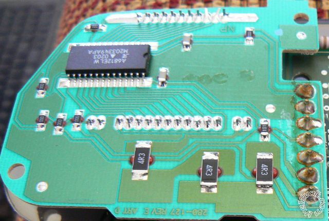
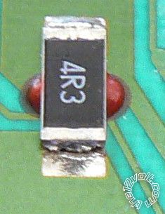
I used a very small, thin blade screwdriver and carefully pried it in the gap of the Front Bezel, carefully pushing it towards the rear of the mirror, and working my way along the mirror. As I approached the lcok tabs the Front Bezel would pop, and move out slightly. I continued working around the mirrors Bezel. Once I had the Front Bezel removed, I removed the Circuit Board along with the Mirror assembly. I looked at the Temperature Circuit board and it was apparent that the Surface Mount Resistor had one side that was not soldered to the Circuit Board. I used 63/37 .050" Solder to to re-solder all three of the Large Surface Mount Resistors.
After half reassembling my Mirror, I tested it and it once again worked.
If you have a similar condition, your problem could be the same.
Thanks.
Larry
ldkraemer 
Member - Posts: 13
Member spacespace
Joined: February 02, 2013
Location: Missouri, United States
Posted: February 02, 2013 at 7:31 PM / IP Logged  
My GNTX-261 Mirror was installed in a 2003 Chevrolet Silverado 2500HD Duramax Diesel Truck.
Attached are the Circuit Board Images, before repair.
Gentex 261 Mirror Repair -- posted image.
Thanks.
Larry
Ween 
Platinum - Posts: 1,364
Platinum spacespace
Joined: August 01, 2004
Location: Illinois, United States
Posted: February 02, 2013 at 7:38 PM / IP Logged  
thanks for the info
ldkraemer 
Member - Posts: 13
Member spacespace
Joined: February 02, 2013
Location: Missouri, United States
Posted: February 02, 2013 at 7:48 PM / IP Logged  
To Test and Troubleshoot your GNTX-261 Mirror:
Test #1
To troubleshoot the Mirror I did a test to see if I could Power it "OFF" & "ON". If I pressed and held the TEMP button for ~9 Seconds the small Green Power LED went off. Likewise depressing and holding the TEMP button for ~9 seconds turned the Power back "ON" to the Mirror.
Test #2
Now, I wanted to test the Auto Diming Feature. During Daylight hours I started the truck, and held my finger over the photoeye that is on the back of the mirror (facing to the front of the truck), while watching the Mirror. It started turning dark, and continued to get dark enough I could barley see anything in the display.
That was about all I could do with my DEFECTIVE Mirror. The Temperature & Compass Indicators were never displayed.
I learned that my Mirror has a 16 Pin Plug that plugs into the back of the Mirror. If you unlatch the plug and remove it from the mirror
so that the latch is to the left and the Lime Green wire is positioned at the Top Right position your wiring is as follows:
1 through 8 on the Left from Top to Bottom, and 9 through 16 on the Right Top to Bottom.
1 - Not used
2 - Not Used
3 - Light Blue
4 - Dark Green
5 - Gray
6 - Light Green w/2 White Tracers
7 - Dark Gray w/2 White Tracers
8 - Black
9 - Lime Green
10 - Not Used
11 - Dark Green w/2 White Tracers
12 - Lime Green w/2 Black Tracers
13 - Yellow
14 - Yellow w/2 Black Tracers
15 - Choc Brown w/2 White Tracers
16 - White with Pink mixed on wire
Actual Wiring Detail is discussed on the previous mentioned forums.
The GENTEX site has good documentation on:
1. AutoDimmingReferenceGuide.pdf
2. CompassCalibrationTroubleshooting.pdf
3. CompassReferenceGuideAndTroubleshooting.pdf
http://www.gentex.com/automotive/product-support/product-support-faqs
Thanks.
Larry
ldkraemer 
Member - Posts: 13
Member spacespace
Joined: February 02, 2013
Location: Missouri, United States
Posted: February 02, 2013 at 8:04 PM / IP Logged  
The sad thing is that I've found hundreds of postings on different Forums requesting information, and help for this specific problem,
with no solution. I took it upon myself to investigate my problem, and post my results.
The GENTEX CORPORATION's information is:
Gentex Corporation - Corporate Headquarters
Investor Relations and Corporate Communications Department
600 North Centennial Street
Zeeland, MI 49464
616 772 1800 - phone
616 772 7348 - fax
http://www.gentex.com
I'm sure they are well aware of the problem as their Case History file is most likely overflowing with duplicate cases of poor Solder Joints.
But, it wouldn't hurt to notify them of your problem, and request
a solution to their Quality Control Problem. You may also want to mention this Forum's Postings.
Thanks.
Larry
ldkraemer 
Member - Posts: 13
Member spacespace
Joined: February 02, 2013
Location: Missouri, United States
Posted: February 06, 2013 at 6:54 AM / IP Logged  
I noticed that my re-soldered mirror needed to be Calibrated, and although I'd had previously Calibrated my Mirror, I couldn't seem to get it in the Calibrate mode.
My Mirror only had the "COMP" & "TEMP" Pushbuttons.
I depressed the "COMP" Pushbutton for ~6 Seconds and it changed to the Zone Display. Arizona is Zone 5, and I wanted to change from the current setting of 2 to 5. The "COMP" Pushbutton changes from a choice of 1 through 15 zones. The secret is that when you depress it to increment to the correct zone, you have to hold it depressed to get the CAL display. For me I just kept Depressing "COMP" until I saw Zone 4. The next Depress of the "COMP" Pushbutton incremented to 5, and by keeping the Pushbutton Depressed my Mirror displayed CAL and started the CAL procedure. I just started my slow ~5 MPH circles in an Empty Parking Lot until the Mirror had calibrated itself.
Larry
ldkraemer 
Member - Posts: 13
Member spacespace
Joined: February 02, 2013
Location: Missouri, United States
Posted: February 09, 2013 at 12:35 PM / IP Logged  
GM 2003 Rear View Mirror Wiring Schematic is available here:
http://www.dieselplace.com/forum/showthread.php?t=374316&page=3
Lrry
ldkraemer 
Member - Posts: 13
Member spacespace
Joined: February 02, 2013
Location: Missouri, United States
Posted: February 12, 2013 at 4:53 PM / IP Logged  
I was told the GNTX-261 Mirror uses a NTC Thermistor, wired to Pin 6
and Pin 7, to sense the temperature. (Negative Co-effiecient Thermistor
decreases Resistance as the Temperature rises.)
Larry
ldkraemer 
Member - Posts: 13
Member spacespace
Joined: February 02, 2013
Location: Missouri, United States
Posted: February 18, 2013 at 3:28 PM / IP Logged  
Another interesting thing I discovered this morning was, while driving in bright sunlight, I put my finger over the Light Sensor that looks forward on my truck. The mirror started dimming, and when it got almost black my Mirror powered off. I thought GREAT, it quit again. So, while I was disgusted I removed my finger, and kept driving. After about 15 seconds I looked at the Mirror, and it was once again powered up, and working. I tried it a second time, and it duplicated the power off event.
Larry
ldkraemer 
Member - Posts: 13
Member spacespace
Joined: February 02, 2013
Location: Missouri, United States
Posted: February 19, 2013 at 10:39 PM / IP Logged  
My 2003 Duramax has a Gentex GNTX-261 Mirror with the two Buttons (COMP & TEMP) (No Air Bag Display, & No Onstar)
When the Mirror is powered "ON" (Left Green LED is "ON") the TEMP Button will:
1. Turn "OFF" the Mirror if held depressed about 8 seconds. Left Green LED will be "OFF"
2. Turn "ON" the Mirror if held depressed about 8 seconds. Left Green LED will be "ON".
When the Mirror is powered "ON" (Left Green LED "ON") , and the COMPASS & TEMP Display is "ON", the Temp button switches from
Degrees F to Degrees C.
When the Mirror is powered "ON" (Left Green LED is "ON") the COMP Button will:
1. Turn "OFF" the Display for Heading & Temperature. Mirror is still Powered up, Green LED "ON".
2. Turn "ON" the Display for Heading & Temperature. Mirror is still Powered up, Green LED "ON".
If you Depress the COMP Button, and hold it a bit the Display changes to the current Zone. Possible Zones are 1 through 15. Each depress
of the COMP Button will increment to the next sequential Zone. If you want to calibrate your Mirror for Zone 5 (AZ) and it is displaying Zone 3,
you will need to increment the Zone to 4 (One Depress of Comp). Then, the next depress needs to be held in until the Zone changes to 5, and
the Mirror switches to CALIBRATE Mode, and Displays CAL. At this point you can release the COMP Button, and start your slow circles in a
parking lot until the mirror CALIBRATES itself. It will exit the CAL Mode when it's finished calibrating.
One other note. On a Sunny Day, if you place your finger over the CDS Sensor that faces forward, your Mirror will start to Darken (Auto Dim)
and continue to darken until it is almost black. At that point it will power off. Removing your finger from the forward looking CDS sensor will
cause the mirror to power back up, and be fully functional in about 10-15 seconds.
At least that's how mine works on my 2003 Duramax.
Page of 3

  Printable version Printable version Post ReplyPost New Topic
You cannot post new topics in this forum
You cannot reply to topics in this forum
You cannot delete your posts in this forum
You cannot edit your posts in this forum
You cannot create polls in this forum
You cannot vote in polls in this forum

  •  
Search the12volt.com
Follow the12volt.com Follow the12volt.com on Facebook
Friday, April 19, 2024 • Copyright © 1999-2024 the12volt.com, All Rights Reserved Privacy Policy & Use of Cookies
Disclaimer: *All information on this site ( the12volt.com ) is provided "as is" without any warranty of any kind, either expressed or implied, including but not limited to fitness for a particular use. Any user assumes the entire risk as to the accuracy and use of this information. Please verify all wire colors and diagrams before applying any information.

Secured by Sectigo
the12volt.com spacer
Support the12volt.com
Top
the12volt.com spacer