the12volt.com spacer
icon

power window motor rest at ground?


Post ReplyPost New Topic
< Prev Topic Next Topic >
wungun 
Copper - Posts: 71
Copper spacespace
Joined: November 27, 2004
Posted: March 25, 2009 at 7:30 AM / IP Logged  

I'm having trouble understanding how my factory Ford express window modules (relays) work by only sending + current to the window motors? Either the window motors rest 'open' or on 'ground' when they aren't used, but it looks like the window switch is switching directly, both + and - to the motor.

When the express modules gets the trigger from the switch for express, I believe ground is being sent to the motor as well, but ONLY while the switch is depressed. When you let go of the switch, the only thing driving the motor is the + from the module...

The module has a thin gauge ground, and a thin gauge 'cancel' lead, which hooks up to the opposite side of the switch...to stop 'express', you tap the window switch in the opposite direction.

It uses heavy gauge wire for the motor lead, the + IN and switch signal IN...

Can someone explain to me how this works without sending a dedicated - current to the motor?

Thanks

howie ll 
Pot Metal - Posts: 16,466
Pot Metal spacespace
Joined: January 09, 2007
Location: United Kingdom
Posted: March 25, 2009 at 8:09 AM / IP Logged  
Didn't I tell you this a long time ago?  It's very simple if it's similar to the Euro Ford system. The switch  sends neg feeds to a processor mounted next to the motor.  The motor is fed with a permanent,  a ground,   a data feed from the GEM box and an ignition trigger or overide. The motor wires run inside the processor or more likely tracks to the motor and that's the point you pick them up.  "I TOLD YOU SO" a couple of months ago but of course you knew better.
wungun 
Copper - Posts: 71
Copper spacespace
Joined: November 27, 2004
Posted: March 25, 2009 at 8:29 AM / IP Logged  

howie ll wrote:
Didn't I tell you this a long time ago?  It's very simple if it's similar to the Euro Ford system. The switch  sends neg feeds to a processor mounted next to the motor.  The motor is fed with a permanent,  a ground,   a data feed from the GEM box and an ignition trigger or overide. The motor wires run inside the processor or more likely tracks to the motor and that's the point you pick them up.  "I TOLD YOU SO" a couple of months ago but of course you knew better.

I'm talking about the North American Focus...the motor is acted upon directly from the switch...

As for using the Ghia (Euro) switch conversion, I designed and made this to make it work in my car using the Ghia switch...

power window motor rest at ground? -- posted image.

It'll drive two windows normally, and two windows in 'express' in both directions...It's compatible with the 530T or the factory Ford express relays (Taurus). I'm gonna use the OE Ford modules because they have a cancel feature built in...I'm not etrirely sure how the 530T 'cancels'.

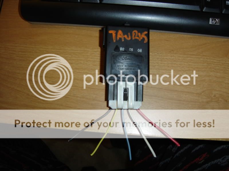
Here is the Ford relay...

power window motor rest at ground? -- posted image.

From right to left, it's:

wire 1 - to motor

wire 2 - to switch
wire 3 - accessory power (12v+)
wire 4 - opposite direction switch side (cancel)
wire 5 - ground

What I'm trying to understand is, how these relays only send 12v+ to the motor, not 12v+ AND ground to run them...the only connection they have to the motor is 12V+.

If wire 4 was hooked up to the MOTOR side of the other lead, and sent 'ground', sure...but the wire is too thin, and it's connected to the switch side, not the motor.

howie ll 
Pot Metal - Posts: 16,466
Pot Metal spacespace
Joined: January 09, 2007
Location: United Kingdom
Posted: March 25, 2009 at 1:34 PM / IP Logged  
I can see your point but I can't answer your question, there was no relay like that in the Euro Ghia, in fact that would take 2 relays,  or that unit is switching 2 other relays, one for up and one for down,  as I said before the Euro version has a processor built on to the motor. Two answer your question, yes in the non-Ghia Euro version the motor wires both sit on ground at rest. What if the motor wires sit on 12v+ at rest? switching neg would then do the trick....just a thought.
wungun 
Copper - Posts: 71
Copper spacespace
Joined: November 27, 2004
Posted: March 25, 2009 at 6:27 PM / IP Logged  

I know some Euro makes have 12v+ at rest....I THINK mine rests 'open', as the + and - are switched at the windows switch, but with the 530T connected, they rest at 'ground'...which really complicates things, especially when the 530 MUST be connected close to the motors to 'see' the feedback they make...

Back to the drawing board I guess!!

Ween 
Platinum - Posts: 1,366
Platinum spacespace
Joined: August 01, 2004
Location: Illinois, United States
Posted: March 25, 2009 at 8:32 PM / IP Logged  

hi,

the window switches motor leads rest at ground on the taurus.  the operation of the express down module i figure is something like this:

the module has accessory feed power from fuse box, ground for electronics, up input...also connects to window motor, down input, and down output to motor.

down input applied... module applies positive voltage on down output terminal, ground applied through window switch to motor. motor rotates one direction.  module measures current drawn by motor.  as motor stalls, current increases..module switches off output.

up input applied... positive voltage applied through window switch, and also at up input.  positive voltage at up input makes module switch down input normally closed.  negative voltage applied through window switch flows through normally closed connection to motor.  motor rotates opposite direction

now if i actually had one in front of me, i'd diagnose further.

m


Sorry, you can NOT post a reply.
This topic is closed.

  Printable version Printable version Post ReplyPost New Topic
You cannot post new topics in this forum
You cannot reply to topics in this forum
You cannot delete your posts in this forum
You cannot edit your posts in this forum
You cannot create polls in this forum
You cannot vote in polls in this forum

  •  
Search the12volt.com
Follow the12volt.com Follow the12volt.com on Facebook
Tuesday, April 23, 2024 • Copyright © 1999-2024 the12volt.com, All Rights Reserved Privacy Policy & Use of Cookies
Disclaimer: *All information on this site ( the12volt.com ) is provided "as is" without any warranty of any kind, either expressed or implied, including but not limited to fitness for a particular use. Any user assumes the entire risk as to the accuracy and use of this information. Please verify all wire colors and diagrams before applying any information.

Secured by Sectigo
the12volt.com spacer
Support the12volt.com
Top
the12volt.com spacer