the12volt.com spacer
icon

2010 mazda 3 door triggers


Post ReplyPost New Topic
< Prev Topic Next Topic >
buddholly 
Copper - Posts: 244
Copper spacespace
Joined: August 24, 2006
Location: United States
Posted: October 15, 2010 at 10:59 AM / IP Logged  
Putting a Viper 5701 in to a 2010 Mazda 3.  On the door triggers according to DirecTechs you must use 10k ohm resistors and 1 amp diodes.  Is it possible to just isolate each door trigger and run them to the green (-) door trigger input (n/c or n/o)??
Velocity Motors 
Moderator - Posts: 12,488
Moderator spaceThis member has made a donation to the12volt.com. Click here for more info.spaceThis member has been recognized as an authority in Electrical Theory. Click here for more info.spaceThis member has been recognized as an authority in Fabrication. Click here for more info.spaceThis member has been recognized as an authority in Mobile Audio and Video. Click here for more info.spaceThis member has been recognized as an authority in Mobile Security and Convenience. Click here for more info.spacespace
Joined: March 08, 2002
Location: Manitoba, Canada
Posted: October 17, 2010 at 10:02 AM / IP Logged  
Individual door pins rest at ground and go to an OPEN state when the door is opened. That is why you need to use the 10K ohm resistor and the 1 amp diode. I'm not sure with the DEI stuff, but with Compustar you can program the door trigger wire to an OPEN trigger.
Jeff
Velocity Custom Home Theater
Mobile Audio/Video Specialist
Morden, Manitoba CANADA
kgerry 
Platinum - Posts: 3,455
Platinum spaceThis member consistently provides reliable informationspace
Joined: February 07, 2004
Location: Saskatchewan, Canada
Posted: October 19, 2010 at 10:40 AM / IP Logged  
the new models of Viper you can do that too.....
Kevin Gerry
Certified Electronics Technician
MECP First Class Installer
Owner/Installer
Classic Car Audio
since 1979
robtrevino 
Member - Posts: 31
Member spacespace
Joined: September 21, 2010
Posted: November 21, 2010 at 3:39 PM / IP Logged  
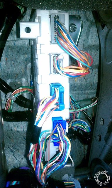
Where you able to do it? I'm trying to find the door pin triggers on my mazda3, 2010 but I've been unsuccessful. I've tried almost all the pins at the BCM and none of them seem to rest on (-) at closed.
What colors and where are they located?
I tried the ones that are explained on this forum, (the blue 24 pin plug on the BCM) but was not able to read it.
robtrevino 
Member - Posts: 31
Member spacespace
Joined: September 21, 2010
Posted: November 21, 2010 at 3:54 PM / IP Logged  
2010 mazda 3 door triggers -- posted image.
mb07 
Member - Posts: 44
Member spacespace
Joined: August 30, 2004
Location: Ontario, Canada
Posted: December 05, 2011 at 5:03 PM / IP Logged  
Hey guys sorry to jump in here but I'm in the same problem. I did a 2 way compustar alarm/remote starter (FT-6000) in a 2010 Mazda 3 everything works fine except the door triggers. I used the RED / white out of the compustar split it into 4 and diode isolated each with the band facing the bcm to the 4 triggers (they all tested fine for each door) but now when I try to force the alarm to go off it does not and from what I'm reading here I need a 10k ohm resistor. Now do I need 4 resistors for the 4 split I did or do I need one to go prior to the split?
tedmond 
Gold - Posts: 4,610
Gold spaceThis member has been recognized as an authority in Mobile Security and Convenience. Click here for more info.spacespace
Joined: January 06, 2007
Location: Ontario, Canada
Posted: December 05, 2011 at 8:40 PM / IP Logged  
the diagram is in downloads. search mazda door trigger. its easier shown from a pic, than having it explained.
Ted
2nd Year Tier 1 Medical School
Still installing as a hobby...pays for groceries
Compustar Expert
mb07 
Member - Posts: 44
Member spacespace
Joined: August 30, 2004
Location: Ontario, Canada
Posted: December 05, 2011 at 11:51 PM / IP Logged  
Alright well I found it.. Kind of wish I didn't lol. 2 questions.. On any sheet it claims this is a negative trigger system and on this diagram it shows to put the trigger from the alarm to a positive. secondly I'm a little confused on how these resistors tie in.. So they do not go inline on my 'new' 4 wires, these actually attach on to it like a T? So one end of the resistor splices in between the 2 diodes and the other end of the resistor goes straight to 12V?

Sorry, you can NOT post a reply.
This topic is closed.

  Printable version Printable version Post ReplyPost New Topic
You cannot post new topics in this forum
You cannot reply to topics in this forum
You cannot delete your posts in this forum
You cannot edit your posts in this forum
You cannot create polls in this forum
You cannot vote in polls in this forum

  •  
Search the12volt.com
Follow the12volt.com Follow the12volt.com on Facebook
Tuesday, April 23, 2024 • Copyright © 1999-2024 the12volt.com, All Rights Reserved Privacy Policy & Use of Cookies
Disclaimer: *All information on this site ( the12volt.com ) is provided "as is" without any warranty of any kind, either expressed or implied, including but not limited to fitness for a particular use. Any user assumes the entire risk as to the accuracy and use of this information. Please verify all wire colors and diagrams before applying any information.

Secured by Sectigo
the12volt.com spacer
Support the12volt.com
Top
the12volt.com spacer