the12volt.com spacer
icon

2004 chevy trailblazer excalibur 1830


Post ReplyPost New Topic
< Prev Topic Next Topic >
dcmtnbkr 
Member - Posts: 25
Member spacespace
Joined: December 11, 2012
Location: Michigan, United States
Posted: December 11, 2012 at 7:05 PM / IP Logged  

Good evening.

I plan to purchase an excalibur 1830-EDPB along with an OmegaLink OL-BLADE-AL to connect in my trailblazer. I've done the research and know where to get to all of the trailblazer wires. I also own and know how to use a DMM and a soldering iron. I was wondering if anyone would be able to assist me with making sure i'm not connecting wires that I don't need to connect. The manuals are listed below.

1830 - http://www.google.com/url?sa=t&rct=j&q=excalibur%201830%20installation%20manual&source...

OL-Blade-AL - http:// www..omegaweblink.com%2Fcommon%2Ffile%2Fget...

From what i can tell, i need to connect everything from the 6 pin power harness, the ground, the hood pin, the siren, and from the blade the orange data wire to the obd2 connector. From there im not sure what else.

shortcircuit161 
Silver - Posts: 556
Silver spaceThis member has made a donation to the12volt.com. Click here for more info.spacespace
Joined: August 29, 2010
Location: United States
Posted: December 12, 2012 at 7:43 AM / IP Logged  
Since you know where most wires go, which connections are you unsure of?
Show me what you have and I will confirm or make corrections to them.
dcmtnbkr 
Member - Posts: 25
Member spacespace
Joined: December 11, 2012
Location: Michigan, United States
Posted: December 12, 2012 at 9:01 AM / IP Logged  
I know where they go, i'm just not sure which ones i need to connect in addition to the ones i've mentioned. Basically, I don't want to duplicate any functions of the blade cartridge. Unless I'm misunderstanding what you are asking me.
lucasoil4u 
Copper - Posts: 317
Copper spacespace
Joined: May 11, 2009
Location: Minnesota, United States
Posted: December 12, 2012 at 9:44 AM / IP Logged  
Well anything that the blade covers I wouldnt hook up dont cut the wires short. leave about 1 foot on there. Try it out make sure everything works and wrap it all up .
dcmtnbkr 
Member - Posts: 25
Member spacespace
Joined: December 11, 2012
Location: Michigan, United States
dcmtnbkr 
Member - Posts: 25
Member spacespace
Joined: December 11, 2012
Location: Michigan, United States
Posted: December 12, 2012 at 1:02 PM / IP Logged  

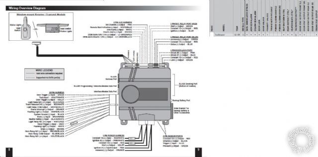
This is what how the module normally looks and the connections needed without the blade. Blade functions are in the box on the right.

2004 chevy trailblazer excalibur 1830 -- posted image.

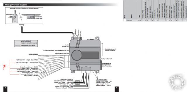
The bottom image is what i think i need to hook up. The wires i am unsure about are labeled with a question mark.

2004 chevy trailblazer excalibur 1830 -- posted image.

dcmtnbkr 
Member - Posts: 25
Member spacespace
Joined: December 11, 2012
Location: Michigan, United States
Posted: December 13, 2012 at 10:00 AM / IP Logged  
Is it neccesary to set up anti grind on this vehicle?
dcmtnbkr 
Member - Posts: 25
Member spacespace
Joined: December 11, 2012
Location: Michigan, United States
Posted: December 14, 2012 at 5:22 PM / IP Logged  

Also, with this alarm do i need a relay for accessory 2 or can i use the dome light wire? This is what the manual says

BLACK/ Red Wire - Light Relay N/O (+/-) Input

This circuit provides the constant feed input for the built-in 10 amp domelight relay. Specifically

the normally open pin (pin 87). This relay can be programmed via installer feature #2 for LOCK,

IGNITION, or ACCESSORY if need be.

CONNECTION: Connect this wire to constant power or chassis ground as needed for the chosen

function.

GREEN/ Violet Wire - Light Relay COM Output

This circuit provides the output for the built-in 10 amp domelight relay. Specifically the common

pin (pin 30). This relay can be programmed via installer feature #2 for LOCK, IGNITION, or ACCESSORY

if need be.

CONNECTION: Connect this wire to the vehicle circuit chosen to be driven. By default, connect to

the vehicle’s domelight circuit.

10 amps be enough?

dcmtnbkr 
Member - Posts: 25
Member spacespace
Joined: December 11, 2012
Location: Michigan, United States
Posted: December 18, 2012 at 12:49 PM / IP Logged  

Hey guys, im  not trying to be a pest but i could really use some assistance. Thanks in advance.

Alarm/RS Module w/blade Vehicle wiring

6-pin main harness, all connections at ignition harness
Red Constant Power | Red
RED / White Constant Power | RED / White
Pink Ignition 1 | Pink
Pink/White ignition 2 | White
Orange accessory 1 | Orange
Violet start + | Yellow
18 Pin Secondary Harness
Green Door Trigger | Cut – Handled by blade
Violet/White Tach input | Cut – Handled by blade
Black Ground | Factory ground, cleaned
< color=#ff0000>Orange Starter interrupt
BROWN / Red brake + | Factory trailer prep controller box, white wire
BLACK/ White neutral safety | Factory Ground
Brown siren out | included siren +
WHITE/ black flashing light (-) out | grey/black at headlight switch
White flashing light (+) out | CUT
Gray hood trigger pin | Hood trigger pin (shouldnt leave disconnected, but can)
Violet door trigger + | Cut/handled by blade
RED / white trunk | cut
BLACK/ Red Wire Light Relay N/O (+/-) Input |12 volt constant from ignition harness
GREEN/ Violet Light Relay COM Output |Brown Accessory 2 in ignition harness
WHITE/ Red Light Relay N/C Input |CUT
Violet/Black Horn Relay N/O (+/-) Input
Blue/Black Horn Relay COM Output
BROWN / Black Horn Relay N/C Input
Blade hook up -
orange - Data | OBDII Purple
The part that is bolded, im not sure if i can do that or not, but it looks like it will work if i program the brain to use that as an accessory, can anyone elaborate?
Im not sure how to hook up the starter interupt or the horn

Also, is there anything that I am missing that needs to be connected?


Sorry, you can NOT post a reply.
This topic is closed.

  Printable version Printable version Post ReplyPost New Topic
You cannot post new topics in this forum
You cannot reply to topics in this forum
You cannot delete your posts in this forum
You cannot edit your posts in this forum
You cannot create polls in this forum
You cannot vote in polls in this forum

  •  
Search the12volt.com
Follow the12volt.com Follow the12volt.com on Facebook
Thursday, April 25, 2024 • Copyright © 1999-2024 the12volt.com, All Rights Reserved Privacy Policy & Use of Cookies
Disclaimer: *All information on this site ( the12volt.com ) is provided "as is" without any warranty of any kind, either expressed or implied, including but not limited to fitness for a particular use. Any user assumes the entire risk as to the accuracy and use of this information. Please verify all wire colors and diagrams before applying any information.

Secured by Sectigo
the12volt.com spacer
Support the12volt.com
Top
the12volt.com spacer