the12volt.com spacer
icon

new installer, first remote start


Post ReplyPost New Topic
< Prev Topic Next Topic >
ss09 
Member - Posts: 3
Member spacespace
Joined: May 15, 2013
Location: Maryland, United States
Posted: May 15, 2013 at 12:58 PM / IP Logged Link to Post Post Reply Quote ss09
hello and thanks for reading, this is my first alarm remote start install i have ever done so be easy on me please. i have a 2002 chevy suburban that im installing a clifford 5102 alarm and remote start. where i am running in to a snag is with the remote start part i have the direct tecs wiring sheets and the remote start owners and install manual. when i installed and hit the remote start button all of the accessories come on but the truck never cranks. also ifi start the truck with the key the alarm siren will chirp. here is what wires i hooked up to the ignition harness.
o     H3/1 Pink (+) Ignition 1 Out & Ign 1 input sense to IGN C6 (Pink) AND DKPLGM Pink
o     H3/2 RED / Wh (+) Ignition 2 to IGN D2 RED / Wh
o     H3/3 Orange (+) Accessory to IGN D1 Orange
o     H3/4 Violet (+) Starter Out to IGN Yellow C1 (harness side of cut wire)
o     H3/5 Green (+) Starter In to IGN Yellow C1 (key side of cut wire)
o     H3/6 Red (+) Ignition 1 In to IGN B5 Red (12V constant)
o     H3/7 Pink/Wh (+) Ignition 2 Out to IGN C5 Pink/Wh
o     H3/8 Pink/Blk (+) Flex Relay In N/A
o     H3/9 RED / Blk (+) Accessory In to IGN B5 Red
o     H3/10 N/C
not sure whats wrong with my install?
ps i am using the dball bypass and the shop i got the alarm from programed it to a 02 suburban
thanks for any help on this
tonanzith 
Gold - Posts: 593
Gold spaceThis member consistently provides reliable informationspace
Joined: July 18, 2008
Location: Washington, United States
Posted: May 15, 2013 at 2:14 PM / IP Logged Link to Post Post Reply Quote tonanzith
The red, red white, and red black are all 12v CONSTANT inputs.
Gary Sather
ss09 
Member - Posts: 3
Member spacespace
Joined: May 15, 2013
Location: Maryland, United States
Posted: May 15, 2013 at 4:14 PM / IP Logged Link to Post Post Reply Quote ss09
tonanzith wrote:
The red, red white, and red black are all 12v CONSTANT inputs.
ok with that being done still dosent start????? think the remote start is bad?
dasbogie 
Silver - Posts: 514
Silver spacespace
Joined: September 30, 2006
Location: Pennsylvania, United States
Posted: May 15, 2013 at 5:17 PM / IP Logged Link to Post Post Reply Quote dasbogie
did you run a tach wire?  if so, did you program it to the viper?  did the dball program to the vehicle?
Advanced
ss09 
Member - Posts: 3
Member spacespace
Joined: May 15, 2013
Location: Maryland, United States
Posted: May 15, 2013 at 5:58 PM / IP Logged Link to Post Post Reply Quote ss09
dasbogie wrote:
did you run a tach wire?  if so, did you program it to the viper?  did the dball program to the vehicle?
yes ran a tac, yes i programed it, and yes to the dball
howie ll 
Pot Metal - Posts: 16,466
Pot Metal spacespace
Joined: January 09, 2007
Location: United Kingdom
Posted: May 15, 2013 at 6:35 PM / IP Logged Link to Post Post Reply Quote howie ll
Double check the ignition, ACC connections and your ground, connect the red, RED / white and RED / black to a constant.
Ah do I here the newbie war cry? "It's a bad unit"
Yeah right.
Do you know the failure rate of DEI,Compustar, A/Voxx?
It's about 0.1%.
How come us pros NEVER EVER see a bad unit, and I will have done 3 x 5704 R/S installs between today and the weekend.
kreg357 
Platinum - Posts: 7,783
Platinum spaceThis member has made a donation to the12volt.com. Click here for more info.spaceThis member has been recognized as an authority in Electrical Theory. Click here for more info.spaceThis member has been recognized as an authority in Mobile Security and Convenience. Click here for more info.spacespace
Joined: January 30, 2009
Location: Pennsylvania, United States
Posted: May 15, 2013 at 8:39 PM / IP Logged Link to Post Post Reply Quote kreg357

H3/1 PINK (+) IGNITION 1 INPUT/OUTPUT     Pink   ( also to bypass module )

H3/2 RED / WHITE (30A) FUSED FLEX Red
H3/3 ORANGE ACCESSORY OUTPUT Orange
H3/4 VIOLET (+) STARTER OUTPUT (CAR SIDE)      Yellow - cut
H3/5 GREEN (+) STARTER INPUT (KEY SIDE)           Yellow - cut
H3/6 RED (+) FUSED (30A) IGNITION 1 INPUT           Red
H3/7 PINK/WHITE (+) FLEX RELAY OUTPUT White   ***Set for IGN2
H3/8 PINK/BLACK FLEX RELAY INPUT 87A                 Not Used
H3/9 RED / BLACK FUSED (30A) ACC/STARTER INPUT         RED / White
H3/10 N/C N/C

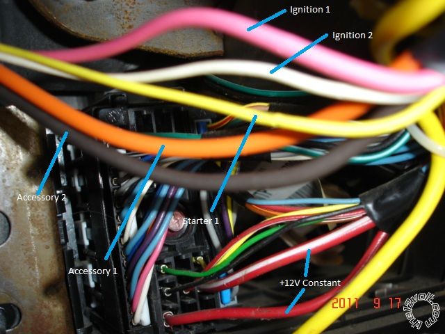
Here is a photo of the wires at / near the BCM :

new installer, first remote start -- posted image.

There is also a Brown ACC2 wire that you might want to connect if you want full accessories

during a remote start.

Not positive which bypass module you are using.  If it is the DLPKGM, are you going D2D or W2W

with the Clifford?  If W2W, do you have the Clifford's (-) 200mA Status Output wire connected to the
DLPKGM's Blue/White GWR input wire?

Soldering is fun!
smokeman1 
Platinum - Posts: 1,588
Platinum spaceThis member has made a donation to the12volt.com. Click here for more info.spaceThis member has been recognized as an authority in Mobile Security and Convenience. Click here for more info.spacespace
Joined: September 14, 2009
Location: Wisconsin, United States
Posted: May 15, 2013 at 8:51 PM / IP Logged Link to Post Post Reply Quote smokeman1
What other wires from the clifford unit are connected and to what.  What wires from the DB-ALL are connected?  Are you doing W2W or D2D?   Did the DB-All program per the instructions?
When all else fails, Read the Instructions
Support the12volt.com Make a Donation
brainsucker 
Member - Posts: 7
Member spacespace
Joined: November 05, 2015
Posted: November 05, 2015 at 12:51 PM / IP Logged Link to Post Post Reply Quote brainsucker
very helpful howie....thanx for your input
brainsucker 
Member - Posts: 7
Member spacespace
Joined: November 05, 2015
Posted: November 05, 2015 at 12:52 PM / IP Logged Link to Post Post Reply Quote brainsucker
in hindsight ..........5102 remotes have to be programmed...default settings are for a manual trans....threw me for a loop at first....THEN I READ THE MANUAL........lol
Page of 2

  Printable version Printable version Post ReplyPost New Topic
You cannot post new topics in this forum
You cannot reply to topics in this forum
You cannot delete your posts in this forum
You cannot edit your posts in this forum
You cannot create polls in this forum
You cannot vote in polls in this forum

  •  
Search the12volt.com
Follow the12volt.com Follow the12volt.com on Facebook
Saturday, April 20, 2024 • Copyright © 1999-2024 the12volt.com, All Rights Reserved Privacy Policy & Use of Cookies
Disclaimer: *All information on this site ( the12volt.com ) is provided "as is" without any warranty of any kind, either expressed or implied, including but not limited to fitness for a particular use. Any user assumes the entire risk as to the accuracy and use of this information. Please verify all wire colors and diagrams before applying any information.

Secured by Sectigo
the12volt.com spacer
Support the12volt.com
Top
the12volt.com spacer