Ok. This might be a very long reply.
First we should start off with a few basic "rules" for auto electronics as applied to the installation of after-market
accessories, like your remote start with keyless entry.
1. It is best to keep the wires short. Besides being neater, this will eliminate parasitic line loss issues that occur
in high current runs and would necessitate larger gauge wire. In-line fuses should be within one foot of their
connection / source.
2. Wherever possible, try to keep the wire connections inside the passenger cabin. This will protect the connections
from the weather, the heat of the engine compartment and the possible rubbing & chaffing if not positioned and
run perfectly.
3. As you have seen looking at the vehicles wiring diagrams, there are multiple places and wires where you can
make your connection to achieve the desired result. As the installer, you can / will decide the exact location.
Typically, installers will look for a place that provides good access for the required soldering tools, while
following Rules 1 and 2 above.
4. The majority of installers will not disconnect the battery during an install. This is to prevent radio preferences
from being lost, reseting computers ( "Not Ready" for state emission inspections ) and other reasons. It
also allows testing / re-testing during the wire connection process. Aside from the main ignition harness
connector, if any connector has to be unplugged, the battery should be disconnected.
5. During the install, running the wires from the control unit to their connection point neatly and then cutting them
to length is an important part of the job. Making a good solder connection and insulating that joint with a quality
electric tape ( Scotch Super 33+ ) is even more important.
6. While planning and preparation is very important, the goal is to install the after-market accessory in a way that
will provide many years of trouble-free use, as efficiently as possible. Most of the engineering of the accessory
is done and appropriate for the vehicles needs. The wires are the correct gauge and long enough for most vehicle
applications. The axiom of K.I.S.S. can come into play. Over thinking an issue can impede the install. The wire
guide listings available from Bulldog Security and Auviovox generally supply the "tried and true" wires and locations.
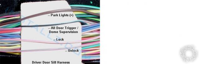
7. One of the most important tools used during the install is the Digital Multi Meter. Even though you have the full
vehicle wiring documentation, you should test and verify each wire before making a connection. Often times a
connection will be easiest by catching the desired wire in a kick panel or door sill but locating that needed wire in a
large wire harness with 40+ wires, with several the same color combination, will be impossible without a DMM.
Here is an example from a Ford F-150 of a typical wire harness...
A few answers to your questions.
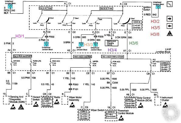
H3/3 is connected to the Malibu's Orange ACC1 wire. As you discovered, there is also a Brown ( ACC2 ) wire. That
wire and this issue have been mentioned many times on this Forum. Here are the two basic thoughts on the Brown
ACC2 wire.
1. It is not absolutely necessary for a remote start install.
A. The vehicle will remote start OK and will not cause any CEL's or damage to the vehicle with it not powered.
B. The Brown wire only powers non-essential items ( like the radio, wipers, power windows, etc ). The Orange
ACC1 wire powers the Heater and A/C circuits that are desired during a remote start.
C. It requires an extra relay and fuses that cost money and consume time during the install.
2. It is best to fully duplicate all normal functions that a regular key start does.
A. Powering the Brown ACC2 wire will ensure that the vehicle is completely fooled into thinking a key was
used to start the engine.
The choice is yours. Both have their own advantages and disadvantages. Your 4206 has a Flex relay output that is
already being used to power IGN2 during a remote start. If you choose to power the Brown ACC2 wire, you will use
the H2/22 Orange (-) Accessory Output wire to control an extra 30/40 Amp SPDT relay that will supply power to this
Brown ACC2 wire.
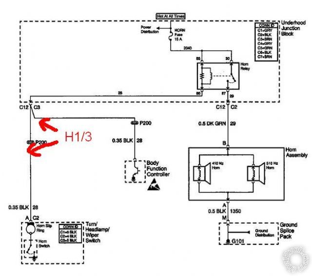
H1/3 Horn wiring. The horn diagram you found / posted shows a BLK ( Black ) wire going from the horn button on
the steering wheel, through the slip ring and leaving the multi-function switch connector at C2. I believe that is the
wire that I incorrectly listed above as "Black @ Ignition switch harness". An error on my part, it should have said
"Black @ steering column". Sorry for the confusion, I was going fast and cutting & pasting.
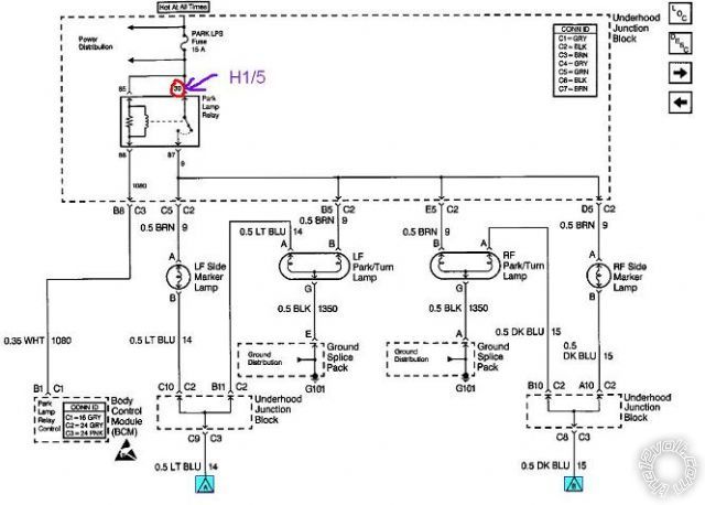
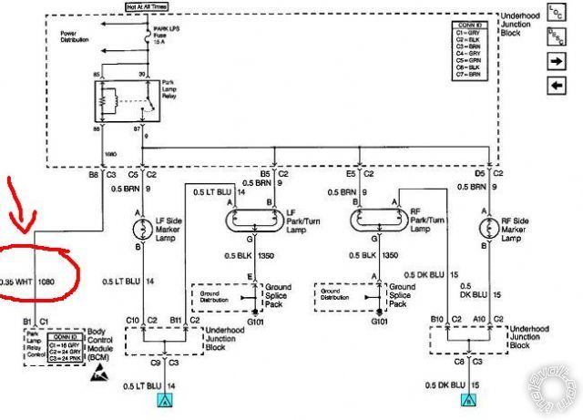
H1/5 Parking Light connection. It looks like the first diagram posted covers only the Headlight function of the switch.
The second diagram shows the Parking Lights after the BCM. Is there another diagram that details the Parking Light
control switch circuit? While I believe that the Brown (+) Parking Light wire is the best and easiest wire to locate and
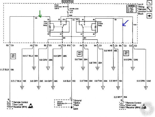
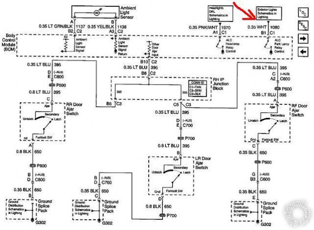
connect to, there is a White (-) Parking Light control wire as noted by this info from Bulldog Security :
PARKING LIGHTS ( - ) WHITE (-) @ BCM, BEHIND PASSENGER SIDE OF THE DASH This is the wire shown in the
second diagram at the BCM. However, while Bulldog does not mention it, this White (-) Parking Light wire might have
to be relay isolated from the BCM to prevent damage to the BCM, but I am not positive about this.
Soldering is fun!


 Topic Closed)


 Also, having a problem with H1/5 BROWN?
Headlamp switch schematic....
Also, having a problem with H1/5 BROWN?
Headlamp switch schematic....
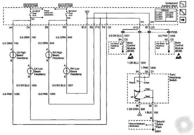 Doesn't show a brown wire in that particular diagram.
But, Front Park/turn and marker lamps diagram... That what I'm looking for? Also stated "***Set for (+)" AS IN? The fuse jumper in the remote start module?
Doesn't show a brown wire in that particular diagram.
But, Front Park/turn and marker lamps diagram... That what I'm looking for? Also stated "***Set for (+)" AS IN? The fuse jumper in the remote start module?
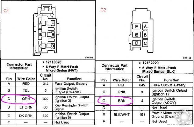 Note C1 cavity C Orange, Ign switch out (ignition 3) were as C2 cavity C Brown is also Ign switch out but labeled ACCY. Hence my confusion since the install guide states (+) ACC out.
Now, I'll admit that I'm not great with wiring. I can work with whats there but when it comes to fully understanding or adding something new then I'm a bit iffy.
Prime example is your #1 and #2 statements. I dont understand the conclusion of extra relay and fuses. How can I understand this? I mean I'd like to understand how to look at a circuit and be able to tell, like in this instance of orange vs brown, which would be a better choice and actually comprehend how and why.
So I'm set then on location of H1/3 Horn wiring.
As far as the H1/5 parking light connection... I stayed up late and must have been euphoric and missed them... I believe these 2 should help...
Note C1 cavity C Orange, Ign switch out (ignition 3) were as C2 cavity C Brown is also Ign switch out but labeled ACCY. Hence my confusion since the install guide states (+) ACC out.
Now, I'll admit that I'm not great with wiring. I can work with whats there but when it comes to fully understanding or adding something new then I'm a bit iffy.
Prime example is your #1 and #2 statements. I dont understand the conclusion of extra relay and fuses. How can I understand this? I mean I'd like to understand how to look at a circuit and be able to tell, like in this instance of orange vs brown, which would be a better choice and actually comprehend how and why.
So I'm set then on location of H1/3 Horn wiring.
As far as the H1/5 parking light connection... I stayed up late and must have been euphoric and missed them... I believe these 2 should help...
 Got a few things I'd like to ask but it'll have to wait till later. Don't want too much clutter at one time.
THANKS,
ROB
Got a few things I'd like to ask but it'll have to wait till later. Don't want too much clutter at one time.
THANKS,
ROB
 Printable version


