the12volt.com spacer
icon

viper 211 hv, mini peterbilt


Post ReplyPost New Topic
< Prev Topic Next Topic >
wanes world 
Member - Posts: 18
Member spacespace
Joined: January 17, 2015
Location: Illinois, United States
Posted: January 17, 2015 at 10:00 PM / IP Logged  
I'm having issues connecting the Viper 211 HV to my project build. The wiring diagram is confusing. Can someone point me in the right direction?
waynes world
tedmond 
Gold - Posts: 4,610
Gold spaceThis member has been recognized as an authority in Mobile Security and Convenience. Click here for more info.spacespace
Joined: January 06, 2007
Location: Ontario, Canada
Posted: January 18, 2015 at 8:21 AM / IP Logged  
vehicle?
Ted
2nd Year Tier 1 Medical School
Still installing as a hobby...pays for groceries
Compustar Expert
davep. 
Gold - Posts: 641
Gold spacespace
Joined: May 27, 2011
Location: California, United States
Posted: January 18, 2015 at 12:00 PM / IP Logged  
The 211 has on-board door lock relays, and 6 wires are associated with the locks. The 211 is about as basic as installs come. Most of the wire functions should be self-explanatory. Get those connected up and the alarm system functioning. Then deal with the locks.
From observation here, some DIY's and novices have difficulty understanding lock system wiring and interfaces. Knowing the vehicle, or what the lock system is if a custom-build, peeps here can tell you the wiring connections for the 6 211's lock wires.
howie ll 
Pot Metal - Posts: 16,466
Pot Metal spacespace
Joined: January 09, 2007
Location: United Kingdom
Posted: January 18, 2015 at 1:23 PM / IP Logged  
Dave, without further info from the OP there's no point in proceeding although we could make an assumption ref Spal/Mes.
wanes world 
Member - Posts: 18
Member spacespace
Joined: January 17, 2015
Location: Illinois, United States
Posted: January 18, 2015 at 5:43 PM / IP Logged  
Guys,
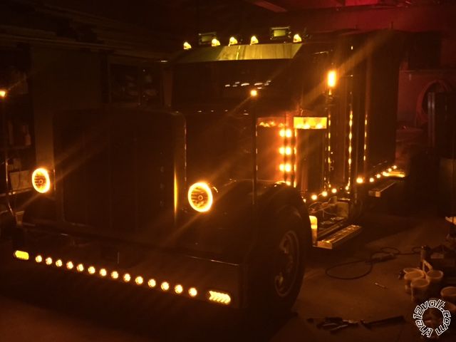
The truck is a conversion to a mini Peterbilt in my garage .
I followed the "directions". The red, yellow & orange are hots. The black is ground. The grn/blk , & the blue/ blk are the wires to the actuators. Violet & violet/blk are hots to the circuits. This is where I can't get the fobs to open or close the locks. I used myPower Probe to check all four actuators & they function well. This is where I'm at now.
The conversion in based on my 96 Dodge 2500 dieiselrace truck.
Is there any ideas?
WAYNES WORLD
waynes world
wanes world 
Member - Posts: 18
Member spacespace
Joined: January 17, 2015
Location: Illinois, United States
Posted: January 18, 2015 at 5:49 PM / IP Logged  
davep. wrote:
The 211 has on-board door lock relays, and 6 wires are associated with the locks. The 211 is about as basic as installs come. Most of the wire functions should be self-explanatory. Get those connected up and the alarm system functioning. Then deal with the locks.
From observation here, some DIY's and novices have difficulty understanding lock system wiring and interfaces. Knowing the vehicle, or what the lock system is if a custom-build, peeps here can tell you the wiring connections for the 6 211's lock wires.
davep,
the unit has 18 wires on the box. I just posted the ones I used but it still doesn't work.
That's why I'm puzzled as to the cause of my issues..
WAYNES WORLD
waynes world
davep. 
Gold - Posts: 641
Gold spacespace
Joined: May 27, 2011
Location: California, United States
Posted: January 18, 2015 at 6:31 PM / IP Logged  
wanes world wrote:
Is there any ideas?
WAYNES WORLD
My responses begin with --
Guys,The truck is a conversion to a mini Peterbilt in my garage .
--Sounds like a cool Project.
I followed the "directions". The red, yellow & orange are hots.
-- red H1/1 = hot at all times
-- Yellow H1/15 = Hot with IGN ON only.
-- Orange H1/16 = ground when armed. You shouldn't need this. Disconnect it.
The black is ground.
-- Black H1/11, correct, is ground.
The grn/blk , & the blue/ blk are the wires to the actuators.
--Correct. Lock and unlock sides of the actuators.
Violet & violet/blk are hots to the circuits.
--These two should be Hot at all times. Fuse them, too.
-- ^^ These 4 connections should now be correct depending on how the manual switches (if any) are wired.
-- If you do NOT have manual switches for the actuators, (this is a stand-alone RKE-only system) then you need to connect:
Brn/blk and the wht/blk wires to Ground.
-- IF you DO have interior manual switches, report back how these are wired to the actuators. You can try it first, but if it blows fuses, we'll have to figure out how the switches are wired. Are they the stock Dodge wiring and switches?
This is where I can't get the fobs to open or close the locks.
-- Connect the brn/blk and wht/blk wires to ground.
-- Some DEI's won't actuate the locks if the IGN is on (the yellow wire) so connect that to an IGN-only source, and try the locks again.
There's some ideas.
I KNEW this was "something special" Howie. That's why I replied the way I did in the first post. Cheers. DP.
davep. 
Gold - Posts: 641
Gold spacespace
Joined: May 27, 2011
Location: California, United States
Posted: January 18, 2015 at 6:59 PM / IP Logged  
davep. wrote:
The 211 has on-board door lock relays, and 6 wires are associated with the locks. The 211 is about as basic as installs come. Get ...the alarm system functioning. Then deal with the locks.
I'm so sorry. This is a Remote Keylees Entry ONLY. No alarm. I installed an Avital 2101 two weeks ago. No wonder the wiring looked familiar. Same thing as your 211. This post should get you straightened out.
````````````````````````````
OK. If you still have the stock 1996 Dodge lock wiring and switches, use this diagram as a guide. Here's the way I would do it.
At the passenger switch, Cut the pnk/blk and orn/blk wires in two.
Connect switch-side pnk/blk to 211 brn/blk.
Connect switch-side orn/blk to 211 wht/blk.
Connect motor-side pnk/blk to 211 blu/blk.
Connect motor-side orn/blk to 211 grn/blk.
Connect 211 violet and violet/blk to FUSED Hot at all times. (Tap the red wire at door switch would be acceptable as well).
I triple-checked the above. It will work, if the Dodge wiring is still in the below configuration.
EDIT: Is this your truck? The red one? 12.94? That's a lot of iron to move that quickly. I'm a Syclone Owner, and don't worry too much about being beat on the street, but I'd loose to you if you had time to spool-up. Pretty cool stuff.
viper 211 hv, mini peterbilt -- posted image.viper 211 hv, mini peterbilt -- posted image.[/IMG]
wanes world 
Member - Posts: 18
Member spacespace
Joined: January 17, 2015
Location: Illinois, United States
Posted: January 18, 2015 at 7:43 PM / IP Logged  
Guys,
I'm looking into these responses. I appreciate the info.
viper 211 hv, mini peterbilt -- posted image.
This is my truck--------
I'll get back with the results -- I hope soon.
Thank You,
WAYNES WORLD
waynes world
wanes world 
Member - Posts: 18
Member spacespace
Joined: January 17, 2015
Location: Illinois, United States
Posted: January 18, 2015 at 8:08 PM / IP Logged  
davep. wrote:
wanes world wrote:
Is there any ideas?
WAYNES WORLD
My responses begin with --
Guys,The truck is a conversion to a mini Peterbilt in my garage .
--Sounds like a cool Project.
I followed the "directions". The red, yellow & orange are hots.
-- red H1/1 = hot at all times
-- Yellow H1/15 = Hot with IGN ON only.
-- Orange H1/16 = ground when armed. You shouldn't need this. Disconnect it.
This is my first order of business--------
The black is ground.
-- Black H1/11, correct, is ground.
This is correct-----
The grn/blk , & the blue/ blk are the wires to the actuators.
--Correct. Lock and unlock sides of the actuators.
This is correct-----
Violet & violet/blk are hots to the circuits.
--These two should be Hot at all times. Fuse them, too.
This is a single wire that is done--------
-- ^^ These 4 connections should now be correct depending on how the manual switches (if any) are wired.
I hope the grn/blk & blu/blk are the wires you speak of-----
-- If you do NOT have manual switches for the actuators, (this is a stand-alone RKE-only system) then you need to connect:
I do have a master switch on the drivers door-----
Brn/blk and the wht/blk wires to Ground.
This appears to be my error------:-(
-- IF you DO have interior manual switches, report back how these are wired to the I do not have any separate switches for the door locks except the master in the drivers door. It is actuators. You can try it first, but if it blows fuses, we'll have to figure out how the switches are wired. Are they the stock Dodge wiring and switches?
This is where I can't get the fobs to open or close the locks.
-- Connect the brn/blk and wht/blk wires to ground.
-- Some DEI's won't actuate the locks if the IGN is on (the yellow wire) so connect that to an IGN-only source, and try the locks again.
I'll move that yellow -----
There's some ideas.
I KNEW this was "something special" Howie. That's why I replied the way I did in the first post. Cheers. DP.
Guys---- check out that lights only photo. This is the project thus far. Stay tuned -----
Thank You,
WAYNES WORLD
waynes world
Page of 3

  Printable version Printable version Post ReplyPost New Topic
You cannot post new topics in this forum
You cannot reply to topics in this forum
You cannot delete your posts in this forum
You cannot edit your posts in this forum
You cannot create polls in this forum
You cannot vote in polls in this forum

  •  
Search the12volt.com
Follow the12volt.com Follow the12volt.com on Facebook
Friday, April 19, 2024 • Copyright © 1999-2024 the12volt.com, All Rights Reserved Privacy Policy & Use of Cookies
Disclaimer: *All information on this site ( the12volt.com ) is provided "as is" without any warranty of any kind, either expressed or implied, including but not limited to fitness for a particular use. Any user assumes the entire risk as to the accuracy and use of this information. Please verify all wire colors and diagrams before applying any information.

Secured by Sectigo
the12volt.com spacer
Support the12volt.com
Top
the12volt.com spacer