Greetings,
I have a 2011 Buick Regal, and am installing the Avital 5303 Security/Remote Start system, with the DBALL2 in D2D mode. I am capable of installing this myself, so I started last weekend. I downloaded all the relevant information for her car from ACDelcoTDS and matched that with The 5303's manual and also the DBALL2's manual. The connections I have made so far are:
Main Harness (H1), 12 Pin connector (Avital 5303)
H1/1 -- RED / White (-) Trunk Release Output -- Not connected.
H1/2 -- Red (+) Constant Power Input -- Attached to 12V constant.
H1/3 -- Brown (+) Siren Output -- Attached to Red Wire coming in from the Siren
H1/4 -- Not Used
H1/5 -- Black (-) Grounded to factory ground bolt in the driver's side kick panel area.
H1/6 -- Violet (+) Door Input Trigger, Zone 3 -- Not connected.
H1/7 -- Blue (-) Instant Trigger Input, Zone 1 -- Not connected.
H1/8 -- Green (-) Door Trigger Input Zone 3 -- Connected to Driver's door window motor wire per DBALL2 manual.
H1/9 -- BLACK/ White (-) Domelight Supervision Output -- Not connected.
H1/10 -- WHITE/ Blue (-) Remote Start Activation Input -- Not connected.
H1/11 -- White (+)/(-) Selectable Light Flash Output -- Not connected.
H1/12 -- Orange (-) Ground when armed output -- Not connected.
Auxiliary harness (H2), 6-pin connector
H2/1 -- Blue (-) Second Unlock Output - Not connected.
H2/2 -- WHITE/ Black (-) Aux 3 output -- Not connected.
H2/3 -- Violet/Black (-) Aux 2 output -- Not connected.
H2/4 -- GREEN / WHITE (-) Factory Alarm Rearm output -- Not connected.
H2/5 -- Gray/Black (-) Wait-to-Start Input -- Not connected.
H2/6 -- Light GREEN/ Black (-) Factory Alarm Disarm output -- Not connected.
Door lock harness, 3-pin connector
Not Connected.
Remote start harness, (H3) 5-pin connector
Not Connected.
Horn, channel 6 (H4), 2-pin connector
Not Connected.
Heavy gauge relay satellite wiring diagram
This is what I'm struggling with. When I read the description of this satellite, and saw the heavy gauge wires, I was led to believe that this goes under the hood, and connects to the power side of the respective relays. So Initially I wired this up as follows:
H/1 -- Purple -- Starter Output to Starter (Starter Side) -- Cut wire going directly to starter motor and connected this to the starter side.
H/2 -- Green -- Starter Input from Ignition Switch (Key Side) -- Cut wire going directly to starter motor and connected this to the "key" side.
H/3 -- Red -- (+) 12V Input -- Connected directly to battery.
H/4 -- Orange -- Output to accessory circuit -- Attached to wire that I had dropped down earlier from Ignition Area -- The original wire is Brown in color.
H/5 -- Red -- (+) 12V Input -- Connected directly to battery.
H/6 -- Pink -- Output to Primary Ignition Circuit -- Connected to ignition run relay under the hood.
H/7 -- RED / White -- 12V Input -- Not connected.
H/8 -- Pink/White -- Output to Second Ignition/Accessory Circuit -- Not connected.
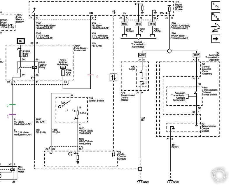
Below is the wiring for the starting and charging circuit under the hood.
The DBALL2 was flashed with the latest GM firmware for my car, and wired for D2D type 1 mode, basically CAN and immobilizer connections, and the accessory output. I setup the Avital to use the 4 pin port for D2D mode as well, and the transponder code was learned by the DBALL according to it's manual (solid green light, then off).
I am having two main problems.
1) The remote start will not work. The engine cranks, but never starts. I have narrowed this down to a couple of possibilities:
a) The DBALL2 never gets the signal that the remote start is trying to start the car. from digging in the forums, this could be due to the status wire not being connected between the DBALL and the Avital. Even though the directions say this is not required in D2D mode, others have found this to be the culprit.
b) The ignition wire on the heavy gauge satellite harness is supposed be connected to the ignition harness at the key switch, and not under the hood. I see that working if the DBALL2 monitors the CAN and sees the engine crank message (if such a message exists) and sends the transponder code.
Assuming b) is the problem, then it's likely I connected the satellite harness wrong. I couldn't find any mention of anyone else connecting the relay satellite in the engine bay and drilling through the firewall to connect it to the brain, for the Avital or any other brand, so it appears it connects right at the key switch. The problem I have with that is that the wires at my key switch go directly to the BCM, and the BCM sends the signal that closes the starter relay, etc. So, I'm slightly uncomfortable with connecting "high current" connections to my BCM.
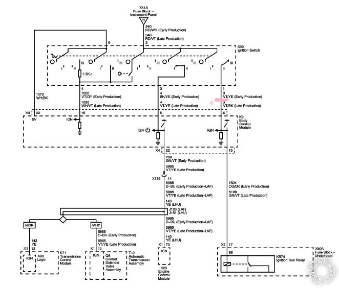
That's my ignition switch, and where the DBALL2 manual says I should hook up the "ignition wire" of the remote starter, which looks like it's #6 on the heavy gauge satellite. GM's documentation confirms that the #1 wire on that connector is the "Run/Crank/Ignition 1 Voltage" wire. I guess I'm confused primarily about whether the heavy gauge satellite is wired at the ignition or under the hood for this car, seeing as how the signals from the ignition are not sent directly to the relays as they are in older vehicles.
2) After connecting the DBALL2, the doors do not lock/unlock with the factory FOB, the Avital FOB, or the button on the instrument panel. The alarm will arm/disarm with both FOBs but the doors have to be locked/unlocked manually. I did not connect the door unlock wire from the Avital because this was supposed to be available via D2D (perhaps the DBALL putting a message on the CANBUS), and that doesn't explain why the vehicle's inside buttons no longer work, although for reference those buttons are also routed to the BCM.
Any helps, thoughts, criticisms are encouraged and appreciated.


 Printable version


