the12volt.com spacer
icon

R/S wont crank mazda6 2004


Post ReplyPost New Topic
< Prev Topic Next Topic >
krizeus 
Member - Posts: 12
Member spacespace
Joined: January 17, 2011
Location: Alberta, Canada
Posted: October 21, 2015 at 12:11 PM / IP Logged Link to Post Post Reply Quote krizeus
Hi, Installed a viper 4105 in mazda6 2004 with Fortin evo all. Lock/unlock and truck release works fine but it won't give me any indication that it's about to R/S ( no crank, crimp). I tried to check my Shutdown diagnostic but it won't give me any lights.
I verified my wiring and they are all solid--solder.
R/S 6 pin
1. Red - constant ---- Black
2. Pink - Output ignition 2 - na
3. Red - constant --- Black
4. Ornage - Output to Acc ----BLACK/ red
5. Purple - Output to starter ---- BLACK/ red
6. Output to Primary Ignition ---Blue
Sat Harness 4 pin
1. Blue - Ground when running --- Bypass module
2. na
3. na
4. na
R/S 5 pins
1. BLACK/ White - Neutral safety switch input ---- grn
2. Violet/white - Tach --- coil -- I measured a AC voltage coming out from that wire
3. Brwon - Brake shutdown ---GREEN/ yel
4. hoodpin -- na
blue/white - na
Min harness 9 pins
1. lt green black - factory alarm diarm
2. GREEN/ wh - alarm disarm
note: bot of the above are wired in Blue wire which also unlock and lock doors. wired with resistor and relay
3. yellow - ignition output --by pass module
4. WHITE/ blue - -activation input -- not connected
5. orange - anti grind when lock -- not connected
6. brown - horn put output- purple white
7. RED / wh - trunk realease - trunk switch
8. Black - ground
9. White - lights flash --lt/green
3 pin (door)
not connected
I assume that if I insert the key in the ignition barrel will R/S my car without programming the bypass.
I also programmed the tach and all good as per as the instruction.
Please help..
kreg357 
Platinum - Posts: 7,783
Platinum spaceThis member has made a donation to the12volt.com. Click here for more info.spaceThis member has been recognized as an authority in Electrical Theory. Click here for more info.spaceThis member has been recognized as an authority in Mobile Security and Convenience. Click here for more info.spacespace
Joined: January 30, 2009
Location: Pennsylvania, United States
Posted: October 21, 2015 at 2:35 PM / IP Logged Link to Post Post Reply Quote kreg357

Possibly a typo but the cars Starter wire is BLACK/ Blue. 

Here what I show for a Viper 4104V :

Viper   2004 Mazda 6

1 Pink   Blue
2 Purple          BLACK/ Blue
3 Orange        BLACK/ Red
4 Red Black
5 Pink/White   BLACK/ White Set Viper to Flex = Accessory  ( Menu 2, Item 6, Opt 2 )
6 Red Black

Soldering is fun!
krizeus 
Member - Posts: 12
Member spacespace
Joined: January 17, 2011
Location: Alberta, Canada
Posted: October 21, 2015 at 5:12 PM / IP Logged Link to Post Post Reply Quote krizeus
Yeah sorry, typo error
Below is how I wired the 6 pins
R/S 6 pin
1. Red - constant ---- Black
2. Pink/white - Output ignition 2 - na
3. Red - constant --- Black
4. Ornage - Output to Acc ----BLACK/ red
5. Purple - Output to starter ---- BLACK/ blue
6. pink - Output to Primary Ignition ---Blue
Set Viper to Flex = Accessory ( Menu 2, Item 6, Opt 2 )
I dont have this option in mine. What I have in Menue 2 option 6 is 2nd ignition behavior - Accessory or ignition
icearrow6 
Copper - Posts: 497
Copper spacespace
Joined: February 02, 2009
Location: California, United States
Posted: October 21, 2015 at 6:58 PM / IP Logged Link to Post Post Reply Quote icearrow6
main harness YELLOW pin# 3 needs to go to the same as the R/S harness pin#6 (pink).
Yellow wire is viper IGNITION input wire.
Also what polarity is your parking lights? does it flash properly with LOCK/Unlock?
krizeus 
Member - Posts: 12
Member spacespace
Joined: January 17, 2011
Location: Alberta, Canada
Posted: October 21, 2015 at 7:36 PM / IP Logged Link to Post Post Reply Quote krizeus
main harness YELLOW pin# 3 needs to go to the same as the R/S harness pin#6 (pink).
Yellow wire is viper IGNITION input wire. --- What are my other option to use as a ignition for the bypass module?.... btw im using Fortin evo all as bypass
Also what polarity is your parking lights? does it flash properly with LOCK/Unlock?
I can't remember but they are working normally.. There is a jumper switch in the R/S to change the positive to negative.---they are working normally..
sparkie 
Platinum - Posts: 2,061
Platinum spacespace
Joined: November 06, 2003
Location: Canada
Posted: October 21, 2015 at 8:09 PM / IP Logged Link to Post Post Reply Quote sparkie
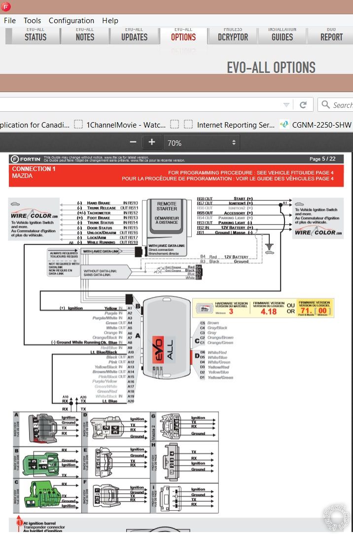
The remote starters RED / White wire should be connected to the BLACK / YELLOW wire in the ignition harness. This is also a battery feed. Running the remote starter's 2 battery wires off only one circuit is not advisable as the current draw is too high. If there are 2 battery feed wires to the factory ignition switch, you should connect the 2 remote starter battery feeds to both wires.
The yellow ignition input wire for the Fortin should be connected to the remote starter's Pink wire (main ignition).
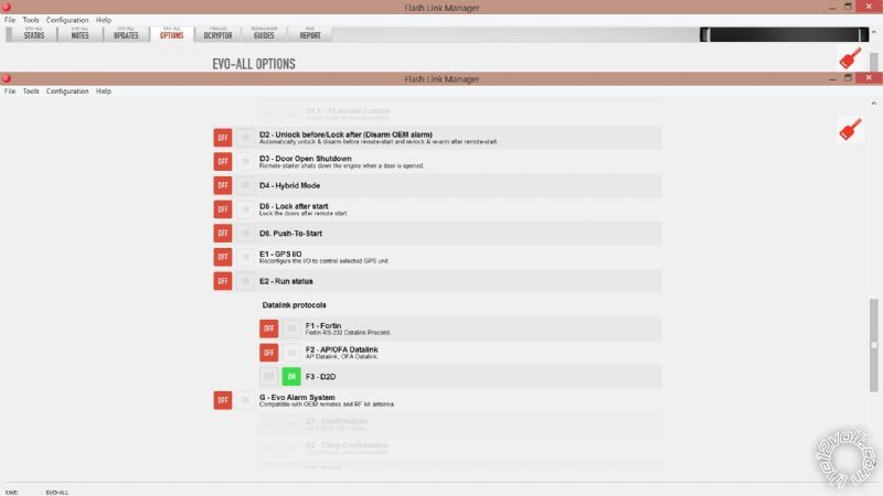
When the Fortin module was programmed, what protocol was used? If you are using the data cable to connect the bypass to the remote starter, you must choose the D2D protocol, otherwise the bypass won't activate during remote start. The default protocol is Fortin and the Viper isn't compatible with this. The bypass will program to the car, but it won't work. The only other way to connect the bypass to the remote starter is the hardwired method if you can't reprogram the protocol. See the bypass installation instructions for with or without Datalink cable.
sparky
krizeus 
Member - Posts: 12
Member spacespace
Joined: January 17, 2011
Location: Alberta, Canada
Posted: October 21, 2015 at 8:27 PM / IP Logged Link to Post Post Reply Quote krizeus
I can try to move the 2nd constant wire and use the pink wire as the ignition for the bypass probably tomorrow.
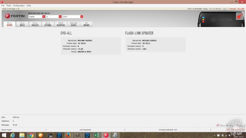
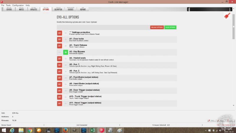
I used D2d protocol during the programming... The thing I'm not sure of is the data port of Viper. I don't see any configuration in google if that is set to accept any bypass manufacturer.
krizeus 
Member - Posts: 12
Member spacespace
Joined: January 17, 2011
Location: Alberta, Canada
Posted: October 21, 2015 at 8:55 PM / IP Logged Link to Post Post Reply Quote krizeus
R/S wont crank mazda6 2004 -- posted image.R/S wont crank mazda6 2004 -- posted image.
R/S wont crank mazda6 2004 -- posted image.
krizeus 
Member - Posts: 12
Member spacespace
Joined: January 17, 2011
Location: Alberta, Canada
Posted: October 21, 2015 at 9:09 PM / IP Logged Link to Post Post Reply Quote krizeus
R/S wont crank mazda6 2004 -- posted image.
krizeus 
Member - Posts: 12
Member spacespace
Joined: January 17, 2011
Location: Alberta, Canada
Posted: October 22, 2015 at 6:18 PM / IP Logged Link to Post Post Reply Quote krizeus
I manage to move the other red wire to black wire ( both 12 volts wire are in different circuit) and tap my yellow wire to the main ignition and still the same problem -- no indication of starting the car, not even a led indication.
Correct me if I'm wrong here---If I put the key in the ignition barrel means it will disarm the alarm and it doesn't require the bypass module. R/S should work right?
Just to give you a brief history where I bought that RS and why.
Vision Electronics is having a big sale of their viper 4105v for only 58 cad dollar. Nobody can't beat that price anywhere. I was wondering if there is something that they can change in the programming or something that will disable the RS so that customer will come back to them for repair. I already tried to reset the the RS twice and still the same problem..
Please help.. this is my second viper already--I probably burnt the door unlock/lock and the alarm arm/disarm port in the first one.
any idea gents?
Page of 2

  Printable version Printable version Post ReplyPost New Topic
You cannot post new topics in this forum
You cannot reply to topics in this forum
You cannot delete your posts in this forum
You cannot edit your posts in this forum
You cannot create polls in this forum
You cannot vote in polls in this forum

  •  
Search the12volt.com
Follow the12volt.com Follow the12volt.com on Facebook
Thursday, April 25, 2024 • Copyright © 1999-2024 the12volt.com, All Rights Reserved Privacy Policy & Use of Cookies
Disclaimer: *All information on this site ( the12volt.com ) is provided "as is" without any warranty of any kind, either expressed or implied, including but not limited to fitness for a particular use. Any user assumes the entire risk as to the accuracy and use of this information. Please verify all wire colors and diagrams before applying any information.

Secured by Sectigo
the12volt.com spacer
Support the12volt.com
Top
the12volt.com spacer