


Viper Model 211HV Installed on 2004 Ford F-250
Home /
the12volt's Install Bay /
Car Security and Convenience / Viper Model 211HV Installed on 2004 Ford F-250
Welcome Guest :)


Posted: December 06, 2016 at 1:38 AM / IP Logged


I decided after unwinding my complete frustration and disappointment with a certain 12v.com member who came to my world offered to help then abruptly scattered away. I have decided regardless I want to help others who may have a similar difficult understanding as I did in how to wire their power locks to a 2004 Ford F-250 XLT Crew Cab or possibly other similar years 1999 thru 2003 Ford F-250 without having OEM keyless entry from the factory such as my truck.
My original thread:
2004 F-250 Super Duty Viper 211HV I won't bother sharing what I think of such people who knock at your door offering to help then abruptly leave you hanging unresolved over a weak excuse.
It actually later turned out the individual did me a big favor as they gave me all the incorrect information about my vehicle pointing my sails heading deeper lost at sea.
First I want a disclosure for this information I'm providing is specific what I did for my specific vehicle and situation which is a 2004 Ford F-250 XLT Crew Cab. Following any of this information and damaging your particular vehicle for any reason and/or in addition neglecting common sense electrical safeguarding procedures such as having correct amperage fuses installed to protect your vehicles circuitry while you install/test your remote keyless system module and wiring harness will be at your own risk.
This information for now is only targeted to share the identifying wires and how to properly connect the remote lock/unlock feature of the Viper Model 211HV keyless remote system to this specific vehicle. I will add later in this thread other features I may connect from the Model 211HV such as parking light flash or horn honk at a later time. The power locks are seemingly always the hardest challenge for most installing remote keyless systems and it sure was a challenge for me.
This explained keyless remote lock/unlock procedure may or may not work with other branded remote keyless systems on the market for a 2004 Ford F-250 or similar vehicle but no guarantee of course.
The Identified Lock/Unlock Motor Actuator wires You'll Need:
Pink/w black stripe wire = Lock ( located passenger side kick panel)
Pink/w light red stripe wire = Un-Lock ( located passenger side kick panel)
Avoid what is all over the web regarding proper lock/unlock wires for the 2004 F-250 which is the Pink / YELLOW & Pink/LT Green. These are not the correct wires to successfully install remote keyless entry as far as the Model 211HV is concerned for this specific vehicle.
Another curve ball. Yes there is another curve ball to narrow down the correct wires you need. You will find duplicate exact colored wires for each or 4 wires total. That is 2 Pink/w black stripe wires & 2 Pink/w light red stripe wires within the bundle of wires behind the passenger side kick panel however only 1 wire of each colored wire mentioned above will be required to connect to the Model 211HV harness.
So which 2 wires of the 4 wires? I have no clue. You will be required to take a quick YouTube lesson about how to use a multimeter to test continuity between wires. If you already know all about how to use a multi-meter you likely already getting tired about me explaining this all out in detail. Sorry all I can say while I continue this for how I wished I could of found this exact information as an inexperienced auto electric individual myself.
Bare with me please. I'll get back to locating the proper wires in awhile after revealing some other important information to help bring this all together.
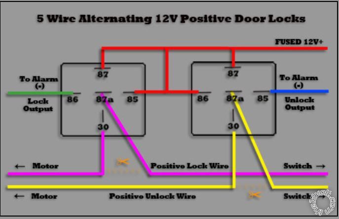
The 2004 Ford F-250 has what is called 5 Wire Door Locks.
5 Wire Door Locks Explained: The door lock switches are wired directly to the motor located in the doors, all wires will rest at ground while the switch is in the off position, excluding the 12 volts. Once the switch is activated to lock the doors it becomes disconnected from ground, 12 volts will be sent to the motor which will lock the doors. Once the switch is activated to unlock the doors the voltage is reversed which in turn move the actuator in the opposite direction.
Note: No additional relays were required as far remote keyless entry concerned connecting the Viper Model 211HV module to my Ford F-250. The Model 211HV has 2 Onboard relays within the module.
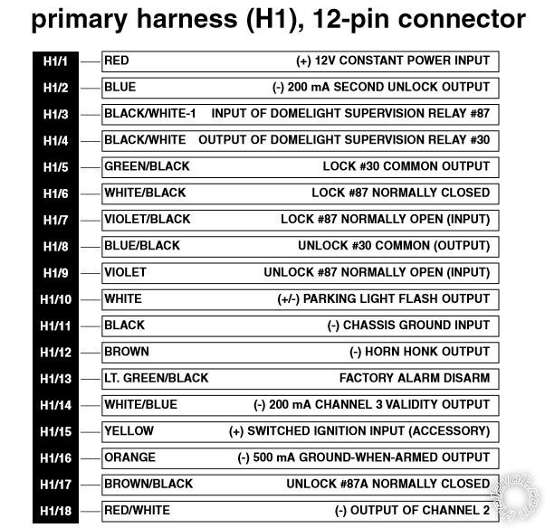
Here is Model 211HV wiring harness & diagram explaining what a remote keyless system would look like to a 5 wire power door lock system applied to such as 2004 Ford F-250:
Model 211HV Harness
 Wiring Diagram Shows Exactly Where To Properly Cut Wires & Interface The Connections
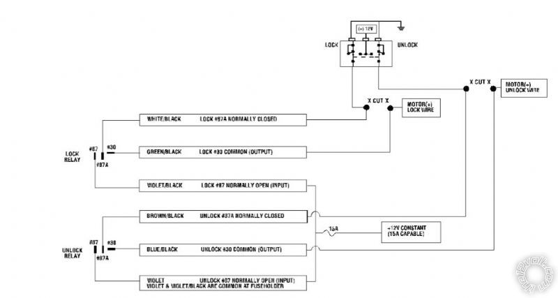 Note: Model 211HV as previously mentioned is equipped with 2 Onboard Relays WithIn The System Module ( this diagram below shows how this looks connected to 5 wire power door lock vehicle from a best perspective of both relays within a remote keyless module such as the Model 211HV
 Getting Back To Finding Proper Lock/Unlock Wires
What I did to find my proper lock/unlock motor wires is cut in half all 4 like wires in the area found behind the passenger kick panel. Use colored tape or whatever to mark each wire end after making the cut. You want to do this so you don't make a mistake rejoining the 2 wires not needed properly once you find the correct 2 wires needed.
I then removed both driver/passenger sides of the trucks door panels in order to complete the continuity probe starting from the kick panel to switch side and motor side lock/unlock wires leading into the actual door. (There are Youtube videos that show how to remove door panels for a Ford F-250).
After cutting the 4 wires you'll have 8 connections now to test for continuity or not. Breaking this down you'll have 4 wires to test heading north upward into the dash or front passenger door and you will have 4 wire connections to test running south to the back seat passenger door.
Hopefully your multimeter will have the beeping feature when continuity is found between wires otherwise you'll have to actually look at your screen each time to see a continuity reading on the meter makeing testing a bit more challenging.
Here is the simplest way to find the first 2 of the 4 wire end connections you'll need. Mark the first 2 wires that have no continuity to either the driver or passenger power door lock switch harness. These 2 wires without continuity are the motor side of the connection just the same as seen in the diagrams above. The even simpler way to find your last 2 connections will be upon that you didn't forget marking the ends of your original 4 cut wires is to take the opposite connecting wire to each of your identified motor wires that had no continuity and that will be your switch side connecting wire. Wala!
Now go back and reference the diagrams above and apply that to what I just outlined for the preparations before making the proper connections between the Model 211HV module harness and the 2004 Ford F-250 for remote keyless wires. My sincere wish to help those better visualize making it much easier for a successful install of the remote keyless portion of the model 211HV. I plan add other explained connections of the Model 211HV a bit later. Until then .... Good Luck!Thank You For Any Help & Your Valuable Time
Getting Back To Finding Proper Lock/Unlock Wires
What I did to find my proper lock/unlock motor wires is cut in half all 4 like wires in the area found behind the passenger kick panel. Use colored tape or whatever to mark each wire end after making the cut. You want to do this so you don't make a mistake rejoining the 2 wires not needed properly once you find the correct 2 wires needed.
I then removed both driver/passenger sides of the trucks door panels in order to complete the continuity probe starting from the kick panel to switch side and motor side lock/unlock wires leading into the actual door. (There are Youtube videos that show how to remove door panels for a Ford F-250).
After cutting the 4 wires you'll have 8 connections now to test for continuity or not. Breaking this down you'll have 4 wires to test heading north upward into the dash or front passenger door and you will have 4 wire connections to test running south to the back seat passenger door.
Hopefully your multimeter will have the beeping feature when continuity is found between wires otherwise you'll have to actually look at your screen each time to see a continuity reading on the meter makeing testing a bit more challenging.
Here is the simplest way to find the first 2 of the 4 wire end connections you'll need. Mark the first 2 wires that have no continuity to either the driver or passenger power door lock switch harness. These 2 wires without continuity are the motor side of the connection just the same as seen in the diagrams above. The even simpler way to find your last 2 connections will be upon that you didn't forget marking the ends of your original 4 cut wires is to take the opposite connecting wire to each of your identified motor wires that had no continuity and that will be your switch side connecting wire. Wala!
Now go back and reference the diagrams above and apply that to what I just outlined for the preparations before making the proper connections between the Model 211HV module harness and the 2004 Ford F-250 for remote keyless wires. My sincere wish to help those better visualize making it much easier for a successful install of the remote keyless portion of the model 211HV. I plan add other explained connections of the Model 211HV a bit later. Until then .... Good Luck!Thank You For Any Help & Your Valuable Time
Wiring Diagram Shows Exactly Where To Properly Cut Wires & Interface The Connections
Note: Model 211HV as previously mentioned is equipped with 2 Onboard Relays WithIn The System Module ( this diagram below shows how this looks connected to 5 wire power door lock vehicle from a best perspective of both relays within a remote keyless module such as the Model 211HV
Getting Back To Finding Proper Lock/Unlock Wires
What I did to find my proper lock/unlock motor wires is cut in half all 4 like wires in the area found behind the passenger kick panel. Use colored tape or whatever to mark each wire end after making the cut. You want to do this so you don't make a mistake rejoining the 2 wires not needed properly once you find the correct 2 wires needed.
I then removed both driver/passenger sides of the trucks door panels in order to complete the continuity probe starting from the kick panel to switch side and motor side lock/unlock wires leading into the actual door. (There are Youtube videos that show how to remove door panels for a Ford F-250).
After cutting the 4 wires you'll have 8 connections now to test for continuity or not. Breaking this down you'll have 4 wires to test heading north upward into the dash or front passenger door and you will have 4 wire connections to test running south to the back seat passenger door.
Hopefully your multimeter will have the beeping feature when continuity is found between wires otherwise you'll have to actually look at your screen each time to see a continuity reading on the meter makeing testing a bit more challenging.
Here is the simplest way to find the first 2 of the 4 wire end connections you'll need. Mark the first 2 wires that have no continuity to either the driver or passenger power door lock switch harness. These 2 wires without continuity are the motor side of the connection just the same as seen in the diagrams above. The even simpler way to find your last 2 connections will be upon that you didn't forget marking the ends of your original 4 cut wires is to take the opposite connecting wire to each of your identified motor wires that had no continuity and that will be your switch side connecting wire. Wala!
Now go back and reference the diagrams above and apply that to what I just outlined for the preparations before making the proper connections between the Model 211HV module harness and the 2004 Ford F-250 for remote keyless wires. My sincere wish to help those better visualize making it much easier for a successful install of the remote keyless portion of the model 211HV. I plan add other explained connections of the Model 211HV a bit later. Until then .... Good Luck!Thank You For Any Help & Your Valuable Time
Posted: December 09, 2016 at 6:56 PM / IP Logged
The next thing I hooked up is my parking light flash. Much easier than hooking up the lock/Unlock wires be sure. Here we go!
This feature flashes your parking lights after your press the Model 211HV keyfob to either lock or unlock your doors. The connection of this wire is quite simple & straight forward. Its the all white wire from the Model 211HV harness and on the 2004 Ford F-250 this white wire hooks into a brown wire behind the parking light switch.
There may be more than one brown wire you'll possibly come across behind the parking light switch as my 2004 Ford F-250 had 2 or 3 brown wires. If you in the same realm a multimeter will be handy required to test the the correct brown wire that gives you a 12v reading upon turning your parking lights on at the switch. That be your correct brown wire in confidence.
My next hook up will be the horn honk. I'll post again when I complete this connection and tell ya how that went.Thank You For Any Help & Your Valuable Time


Posted: December 09, 2016 at 7:15 PM / IP Logged
Very through with plenty of good info. Thanks for sharing!
While your truck did not follow the published info on the Door Lock wires, other wires seem to be normal. Here is
a link to a Pictorial on this gen Super Duty : https://www.the12volt.com/installbay/forum_posts.asp?tid=133810 It
might be helpful, especially on the Horn wire because one on the places to locate it is in the Air Bag harness and
connector.
Directed wrote a Tech Tip guide that a lot of installers have found very helpful when identifying and working with
the various Door Lock systems commonly found in vehicles. Plenty of good info with diagrams. Here is a link :
https://www.the12volt.com/installbay/file.asp?ID=1213Soldering is fun!
Posted: December 10, 2016 at 8:24 PM / IP Logged
Thank you kreg357 for the kind comments and the added information. The horn honk connection looks to be straight forward as well. I've yet have to make the horn connection. The Viper Model 211HV is a fairly basic system featuring mainly remote lock/unlock. This system don't have an alarm but equipped with the panic feature horn honk. I picked the Model 211HV for the name and quality recognition of viper products. The style and design of the key fobs are of good quality .
I like to try and explain maybe a little better about the lock/unlock wires on these surrounding years 2004 Ford F-250s. What is commonly published and found all over the web for this vehicle's wiring diagram regarding proper colored lock/unlock wires for connecting your keyless system harness are the Pink / YELLOW Stripe Wire & Pink/Light Green Stripe wires.
As far as my 2004 Ford F-250 was concerned I identified to confirm these particular wires connected through each driver/passenger kick panels and also ran into the lock/unlock switches drivers/passenger sides. I also said however that these were not the correct wires for connecting into your remote keyless remote system.
After grueling trial and error & multi-meter testing I discovered these wires Do Not run to the lock actuator motors at either door and that is specifically why they're not the correct lock/unlock wires to hook to the Model 211HV. I traced the wires and learned they connected both drivers/passenger lock/unlock switches thus making them both work essentially as master switches. So in other words my truck per say reiterated you have the ability controlling all locks with either the drivers or passenger lock/unlock switch. This further means you may mount your keyless remote module either under the drivers side or passenger side. I chose mounting my module under the glove box bottom panel above the floor board on the passenger side for my 2004 Ford F-250. The drivers side is harder mainly because the emergency brake and other brake/gas pedals are pitas and just make it more difficult for mounting another accessory to your truck.
I actually removed my door panels off drivers/passenger sides so I could not only preform continuity tests of the lock/unlock motor wires I actually could also physically see to conclude that the Pink / YELLOW & Pink/light green lock/unlock switch wires in no way lead to either actuator motor.
The exampled wiring diagrams above clearly outline you want the 2 lock/unlock wires that run from the actuator motor and switch. In my case that was the Pink/black stripe wire & Pink/light red wire I wanted.
I hope I explained in this thread for a better understanding about the 2004 Ford F-250 having a unique Type C or 5 wire door lock system and exactly how to interface not only a Viper Model 2111HV but hopefully most of my explanations will also work just the same using other branded keyless remote lock/unlock systems.
Will post in the coming days when I get around hooking up the horn panic feature.Thank You For Any Help & Your Valuable Time
Posted: December 11, 2016 at 4:07 PM / IP Logged
I now connected the - output solid brown colored wire from the model 211HV harness to my - output solid blue colored wire beneath the steering column on my Ford F-250 ..... and bingo horn panic feature via pressing horn symbol on remote key fob works without a hitch!
Note: Be informed that the horn button on the model 211HV remote key fob must be pressed and held pressed for about 2 or 3 seconds having a short delay before horn panic activation begins. The delay is quite nice so you don't activate the horn panic at every time you may accidentally press the horn on the key fob. Once horn honk activation begins you can stop the horn when ready simply by pressing the key fob horn button again and horn will stop honking.
At first I thought I was going to be required to interface with a relay because of the delay. Don't bother on the 2004 Ford F-250 not required. The horn is a - trigger matching perfectly to interface with the viper Model 211HV - horn wire output.
I don't get a quick and short horn beep as I expected when either locking or unlocking the doors on my 2004 Ford F-250 however. That being for what ever reason I'm 100% satisfied and gonna quit as I have a parking light flash whenever I lock/unlock and I have horn panic if I ever want to draw surprise attention for any reason I see may need to.
This was a real challenge for me as I'm not at all an electrical person but I enjoyed tackling this project and enjoyed being able to share how I did this hoping in the days/months or years to come this thread will remain to help others in need. God Bless! Let us hope Trump will make America Great Again!
Thank You For Any Help & Your Valuable Time
Posted: December 11, 2016 at 4:21 PM / IP Logged
Hi,
The blue wire has been tested to show a ground when the horn button is pressed, correct? A jumper wire to this connection and ground should activate the horn, does it? If yes, using the ammeter function of your multimeter, connect the same as the jumper wire and measure DC amps drawn. Since the 211HV horn output is 200mA max, the vehicles horn relay coil current draw needs to be checked to see if it is within range. If it is within range, does the panic function on the remote activate the horn?
Also, the users manual (found online) states a second press of the lock or unlock buttons within 5 seconds should honk the horn..page 8. And audible mode (AUX and then lock or unlock) enables confirmation honk..page 11.
Hope this helps.
Posted: December 11, 2016 at 5:19 PM / IP Logged
I really appreciate you trying to help troubleshoot my problem. I got the horn working easily. It was me being a dufus by not understanding there is a short delay with pressing horn symbol panic mode using key fob to minimize whenever you may accidently hit horn key fob button and immediately having horn honk.
Thank You For Any Help & Your Valuable Time
Posted: December 21, 2016 at 10:32 AM / IP Logged
I'm back again with another feature from the Viper Model 211HV I didn't mention earlier for which I also hooked up to my 2004 Ford F-250.
Dome Light Supervison
This triggers the dome light in my truck to come for about 30 secs upon pressing unlock on the key fob. On the 2004 Ford F-250 to get this working all I did was take the H1/3 BLACK/ White wire from the Model 211HV module wiring harness and connected it to my 12v source. I then tapped the H1/4 wire from the harness module connecting that into the BLACK/ light blue striped wire located beneath the truck's passenger side kickpanel.
Here is another tidbit I'll share that some of you reading may also want to apply to your Ford F-250. This is not required but I personally like organization & wanted all fuses associated with accessories I added where I could easily get to them in any event of electrical overload therefore could easily access and replace a fuse.
I purchased a small 6 terminal auto fuse box from Autozone and mounted this nicely within my trucks glovebox. I ran my main 12v wire from my truck's battery through the engine compartment then through firewall yada..yada and neatly under the dash leading to behind the glovebox compartment area. I then drilled 3/4" holes or so holes in the actual backside of glovebox near the chosen area I mounted the fuse terminal in order to neatly accommodate running all my 12v connections through the drilled holes & easily connect to the fused terminal.
If you don't want to drill holes in your glovebox you may run your 12v connecting wires over the top backside lip of the glovebox. Whichever you choose keep in mind any 12v connecting wires meant for the terminal have enough slack so whenever you'll open or close the glovebox ensuring wires never tense to get disconnected. There is plenty of free open space behind the 2004 Ford F-250 glovebox that easily enables leaving some slack wires.
The fuse terminal in the glove box made my project so much cleaner and neat and even better having a couple connections left unused for other 12v accessories I may choose adding in the future. The Model 211HV was 90% all connected in the glove box area and the passenger kick panel as a result me adding the 12v fuse terminal.
The only 2 connections from the model 211HV harness requiring me to run back to drivers side area were the H1/10 white parking light flash wire and the H1/12 brown horn honk wire.
One last thing about the horn honk I need to mention. I said earlier the horn panic works with a delay after pressing the horn symbol on the key fob. I also discovered the horn will also do a short beep ever slightly whenever you press the lock on the key fob however this only occurs by pressing the lock symbol on key fob a second time.
In other words whenever you lock the doors with using the key fob no horn honk. Press lock immediately again after initial 1st time and then you'll get a short horn honk. My original expectation was the system would initiate a short horn honk upon pressing lock on key fob the 1st time but as outlined pertaining my installation that is not the way it works. If this is the correct way it works or not I have no clue but never the less I'm done and completely satisfied with the outcome.
When all said and done it cost me more money than to have it installed by an outside professional because I purchased many tools such as a multi meter and soldering iron and many other small things not worth mentioning. So to be honest if you neither have the tools or see yourself ever doing this again in the near future it may be better just let a pro do it when the all mighty dollar and senses come to play.
The gratification doing it for yourself is you do it the way you desire in a custom way and in the care for which you want it installed vs. the know it all pro installing it with T Tap connectors that may or may not last over time instead of more reliable connection using solder. Naturally their best interest doing it fastest way to make a buck and move on to another installation. It's been my experience nobody cares about your vehicle more than you and if you like this sort of thing and conquering something you never have before and gaining the knowledge of life makes it all worth it.Thank You For Any Help & Your Valuable Time

Posted: December 22, 2016 at 1:03 AM / IP Logged
Just to clarify...
You truck didn't come with power door locks. So you used the aftermarket keyless entry alarm to interface with the Lock/Unlock Motor wires on your F250 to allow you to use the keyless fob of the Viper Model 211HV to control the door locks.
Is that correct?
f250owner wrote:
|
Posted: December 22, 2016 at 3:25 AM / IP Logged
I hope I wasn"t really this unclear explaining this thread by your question. Apparently I was. My 2004 Ford F250 came equipped with power door locks (5 wire) from factory however without a remote keyless entry system.
The Viper Model 211Hv remote keyless entry system as explained in this thread worked perfectly to accommodate my desire for adding remote keyless entry to my Ford F250 truck. I hope I was able to have clarified your question.Thank You For Any Help & Your Valuable Time
 Printable version
| You cannot post new topics in this forum You cannot reply to topics in this forum You cannot delete your posts in this forum You cannot edit your posts in this forum You cannot create polls in this forum You cannot vote in polls in this forum |

| Search the12volt.com |
Follow the12volt.com 
Friday, April 19, 2024 • Copyright © 1999-2024 the12volt.com, All Rights Reserved • Privacy Policy & Use of Cookies

Friday, April 19, 2024 • Copyright © 1999-2024 the12volt.com, All Rights Reserved • Privacy Policy & Use of Cookies
Disclaimer:
*All information on this site ( the12volt.com ) is provided "as is" without any warranty of any kind, either expressed or implied, including but not limited to fitness for a particular use. Any user assumes the entire risk as to the accuracy and use of this information. Please
verify all wire colors and diagrams before applying any information.
